Build Your Own
Smart Chess Board
A complete step-by-step guide to building an ESP32-powered chess board, 100% DIY, with LED move indicators, hall-effect piece detection, Stockfish AI, and Lichess online play.
Get Started → View on GitHub
Materials Required
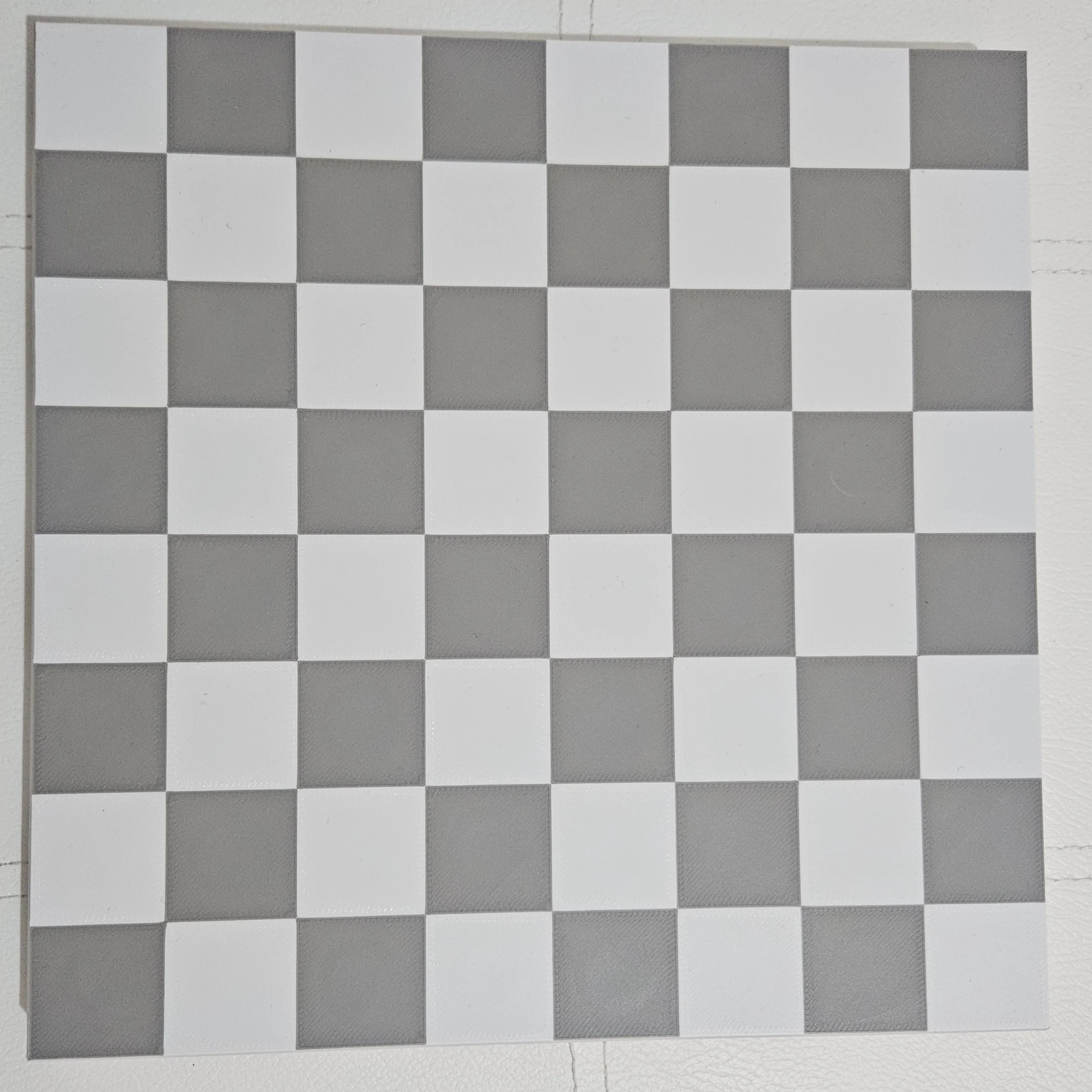
Board + Plastic PCB
Print the board and plastic PCB from MakerWorld
ESP32 Dev Board
Any cheap ESP32 board - the brains of the chess board
WS2812B LED Strip
30 LEDs/m, ~3 meters - lights up each square
A3144 Hall Effect Sensors
64 pcs (TO-92 package) - one per square to detect pieces
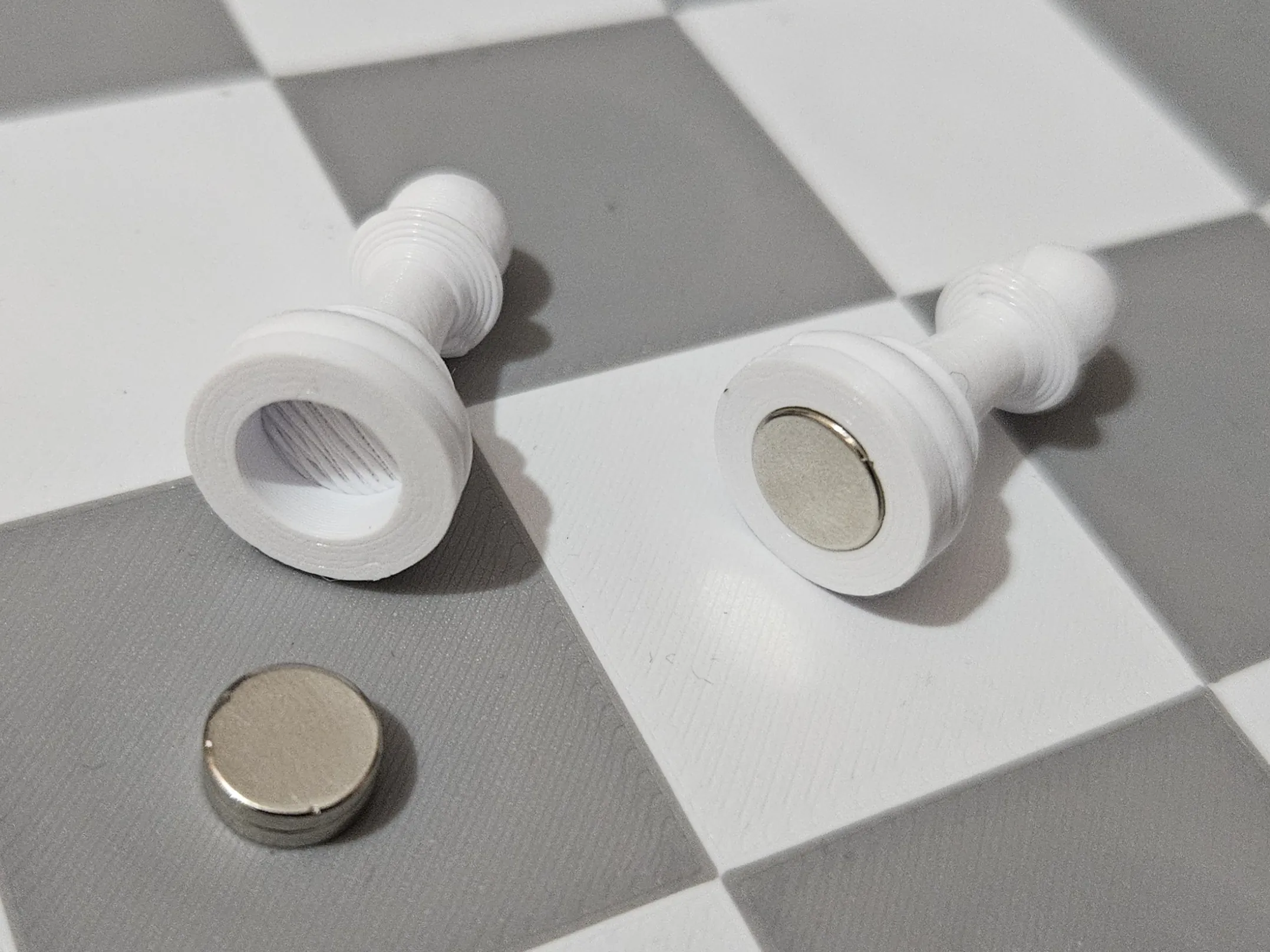
Neodymium Magnets
8×4mm (32 pcs) or 8×2mm (64 pcs, stack 2) - embedded in chess pieces
Iron Discs 12×1mm
64 pcs - placed under the board to hold pieces and spread magnetic field for reliable detection
74HC595 Shift Register
1 pc - drives the column scanning
USB-C Female Port
1 pc - for powering the board without having the ESP32 USB port hanging off the side
Resistors
8 pcs 10k Ohm - pull-up resistors for the hall effect sensors outputs + 8 pcs 1k Ohm - for the PNP transistors' base
Level Shifter (3.3V→5V)
4-channel - for LED data and shift register signals
PNP Transistors
8 pcs (2N3906, BC557, etc.) - for powering A3144 sensor columns from shift register
Schematics
These diagrams show how to connect all the electronic components together. Study and understand them before you start soldering.
Full Circuit
Interactive circuit diagram. Zoom and pan using the scroll wheel and left/right click. Hover on a pin to show the label. View the project on Cirkit
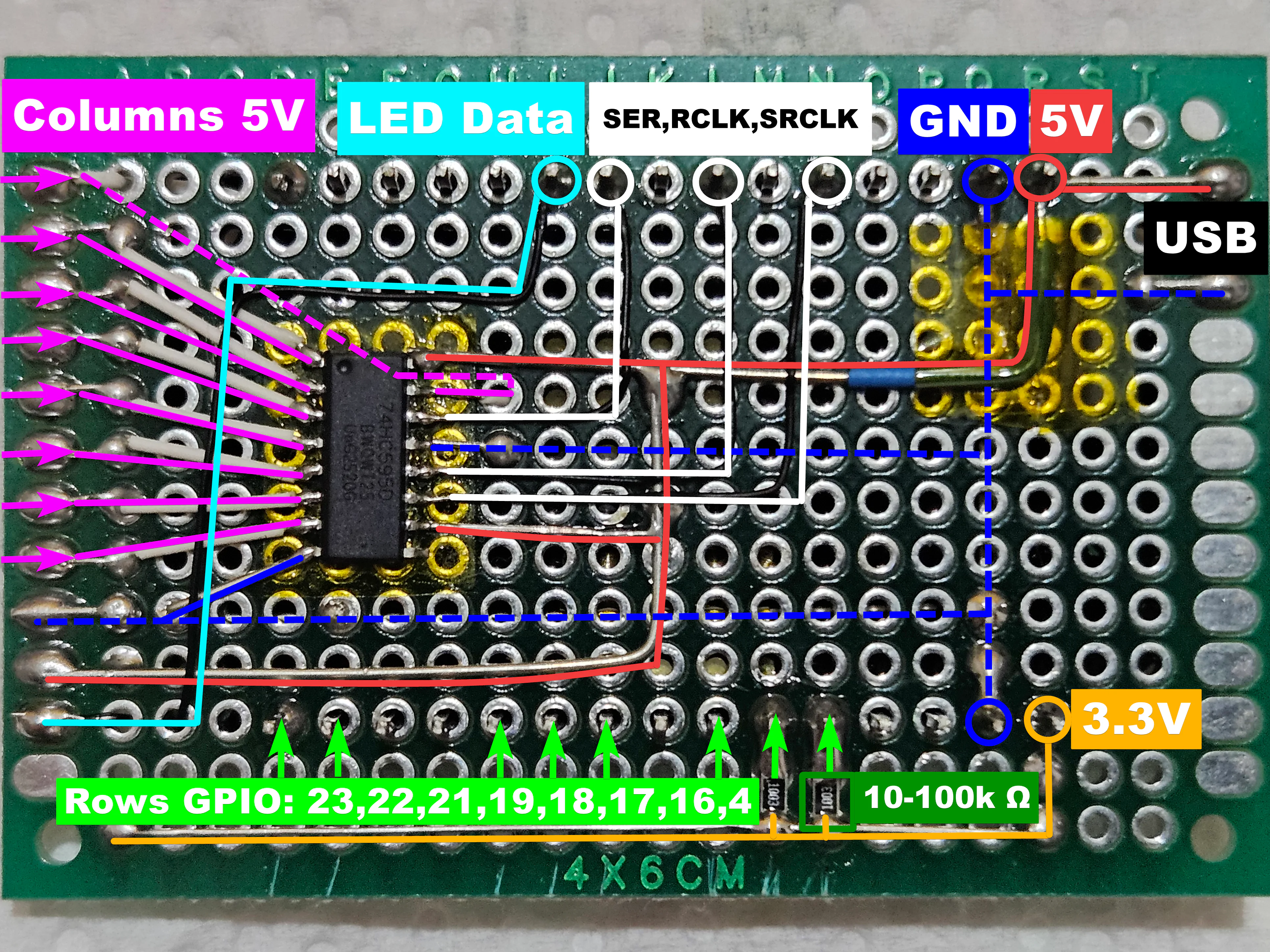
ESP32 + PCB Wiring
Overview of the ESP32 connected to the main PCB - showing shift register signals, sensor rows/cols, LED data, pull-up resistors and power lines.
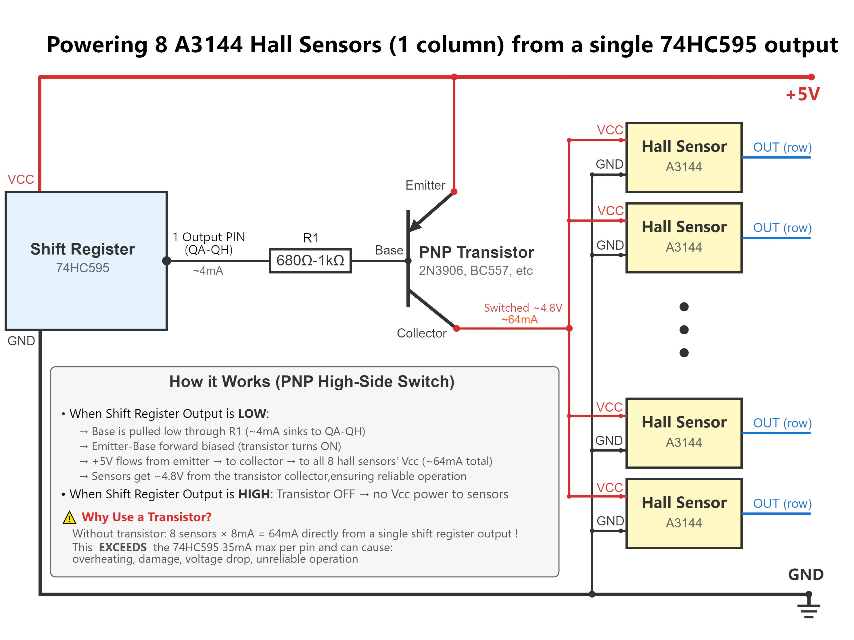
Transistor Circuits - Column Drivers
PNP transistors should be used to switch 5V power to each sensor column via the shift register outputs. This prevents voltage drop and protects the shift register from overcurrent. If you don't use them, don't be surprised when the magnets aren't detected. I didn't use them for my own prototype because I just copied the original Concept-Bytes PCB 1:1, it luckily worked for me but as soon as other people started building it and having issues, that's when we realized the original PCB design is REALLY BAD !
 PNP Configuration
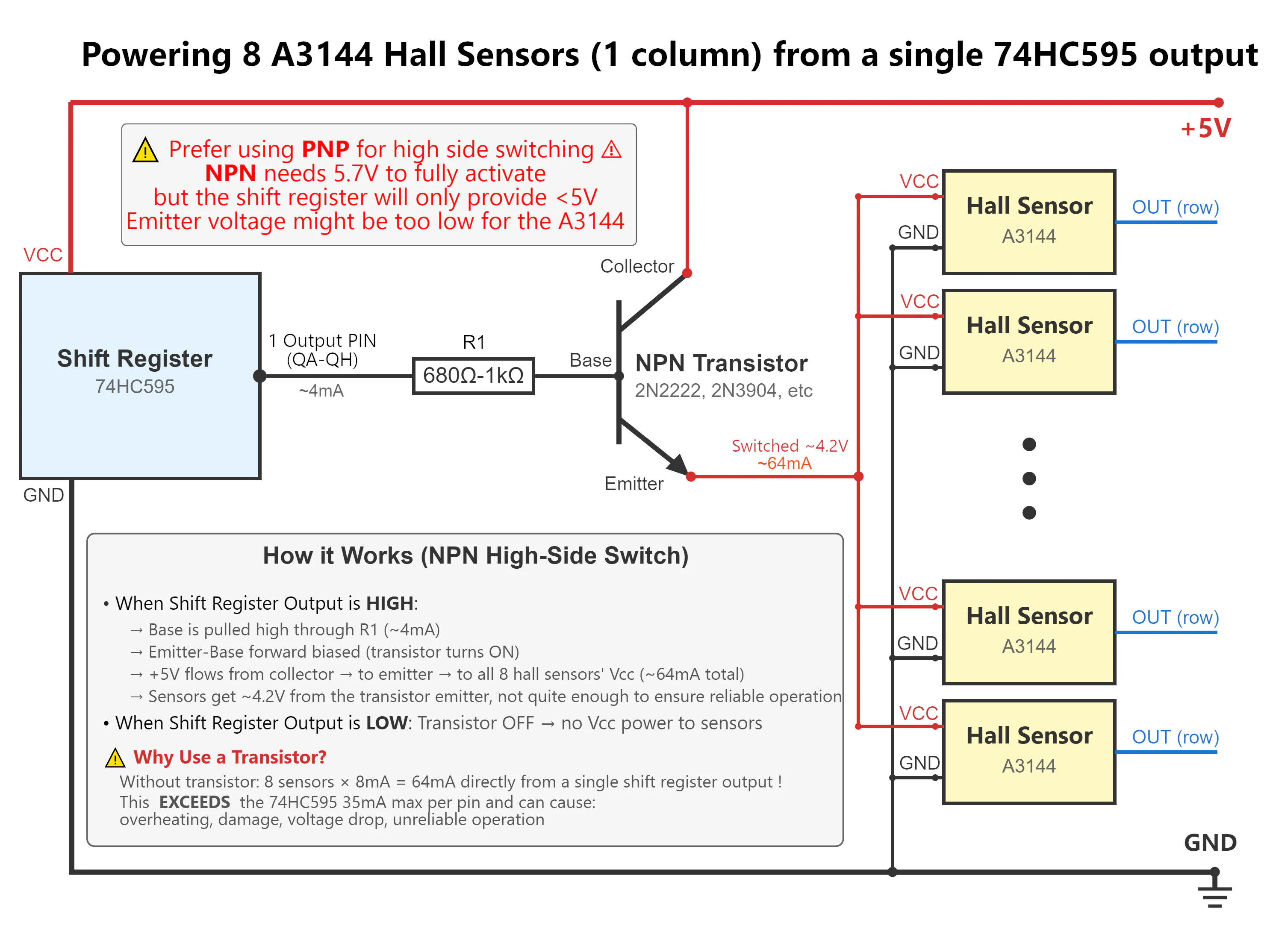 NPN Configuration
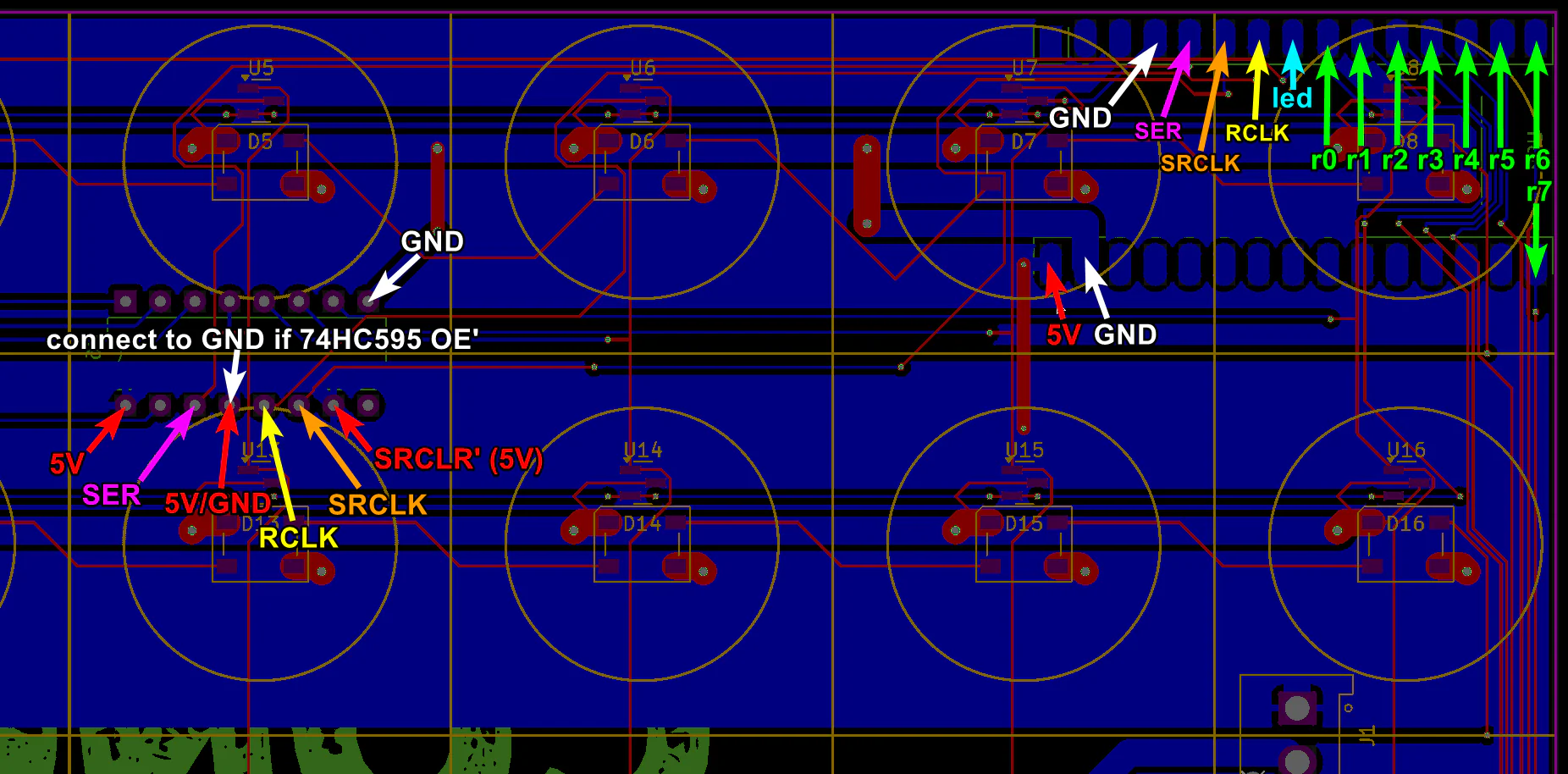
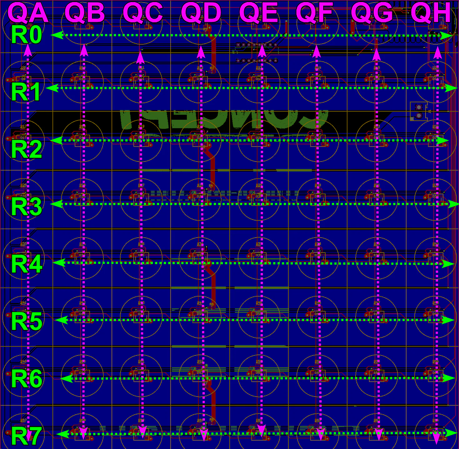
Original PCB Layout
The original Concept-Bytes PCB design, useful if you want to connect the ESP32 to it
Step 1 - PCB Overview
Get familiar with the main PCB before we start on the board itself. This is where the ESP32, shift register, transistors, and connectors live.
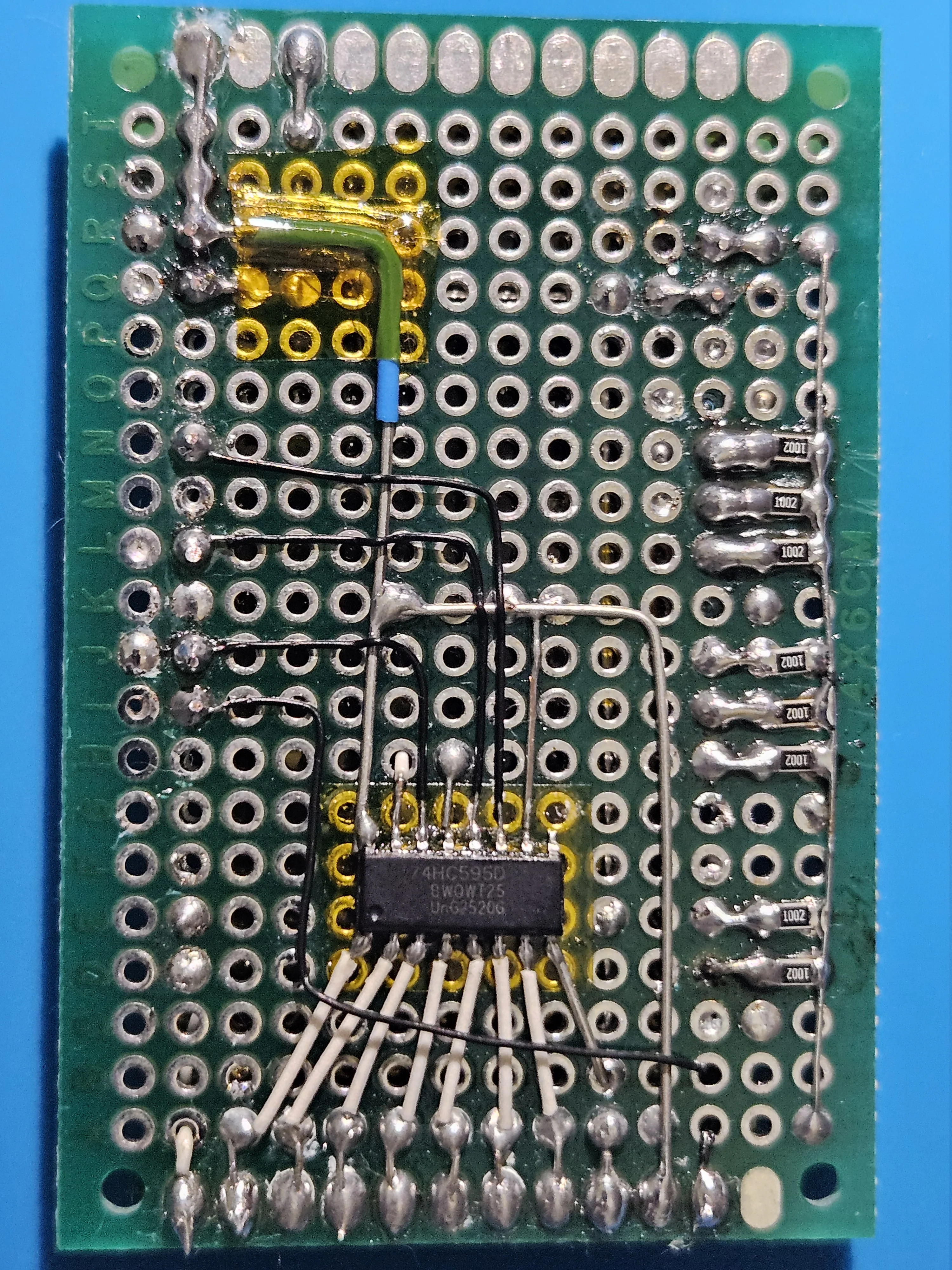
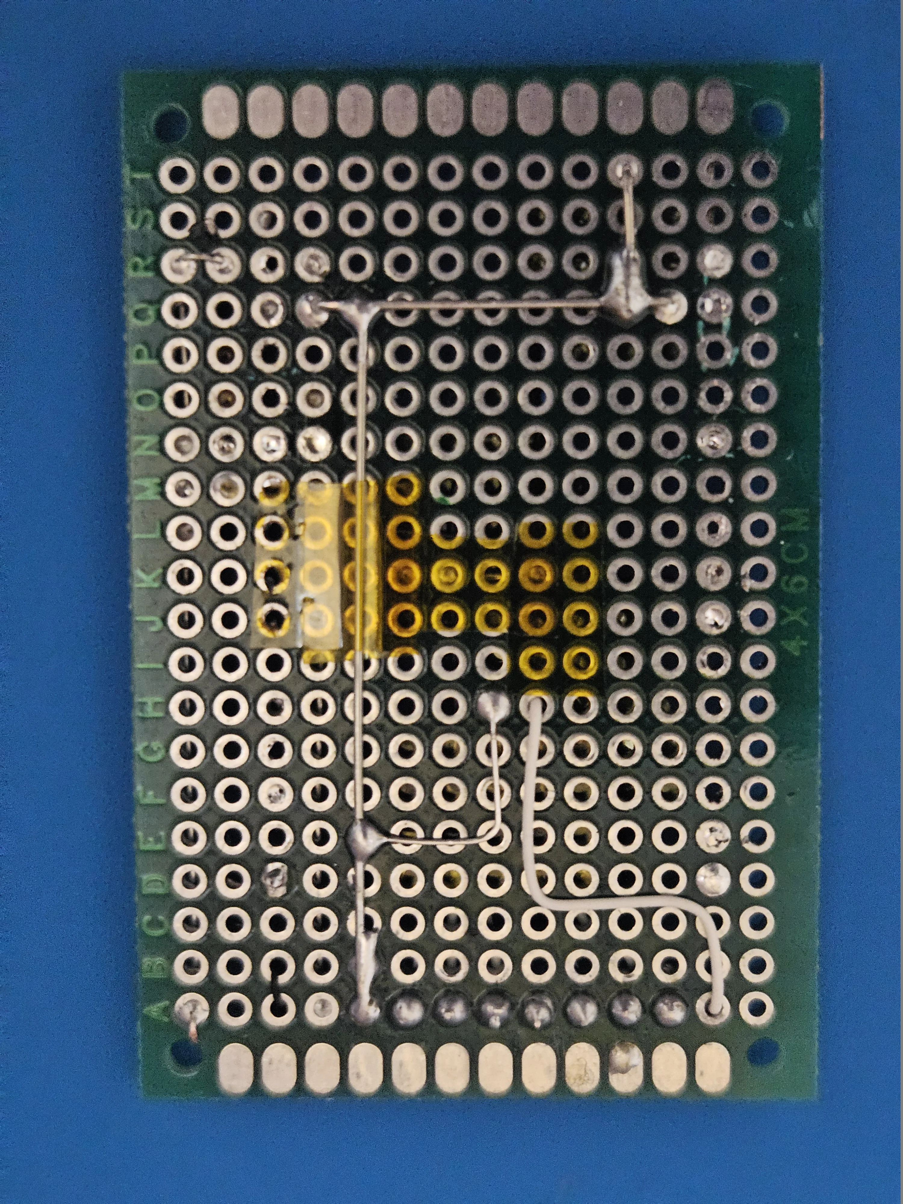
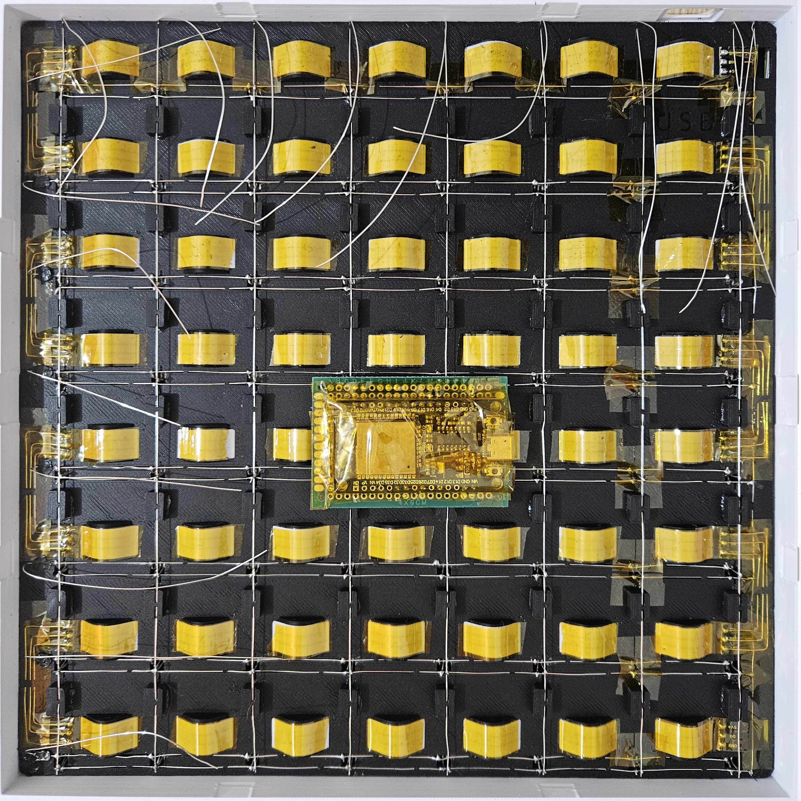
PCB Bottom Side
Build and test the PCB, following the schematics above. This is mine, notice it doesn't use transistors nor a level shifter, but they're highly recommended for reliability.
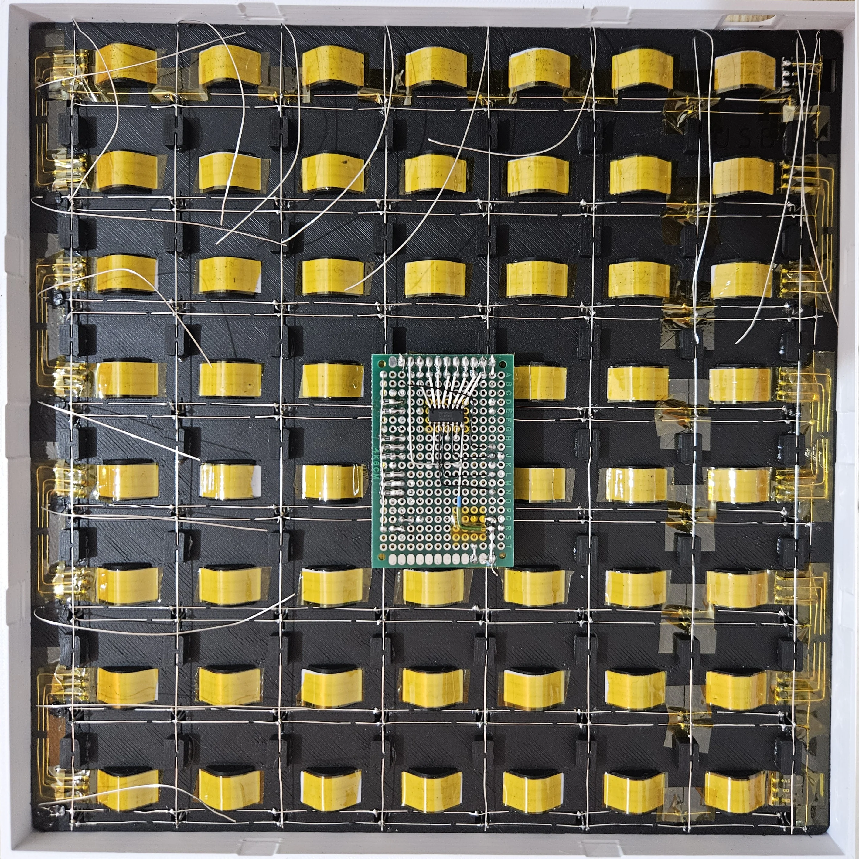
PCB Top Side
Top view of the PCB with and without the ESP32 mounted. GND and Shift Register QA are routed on this side.
 PCB top view without ESP32
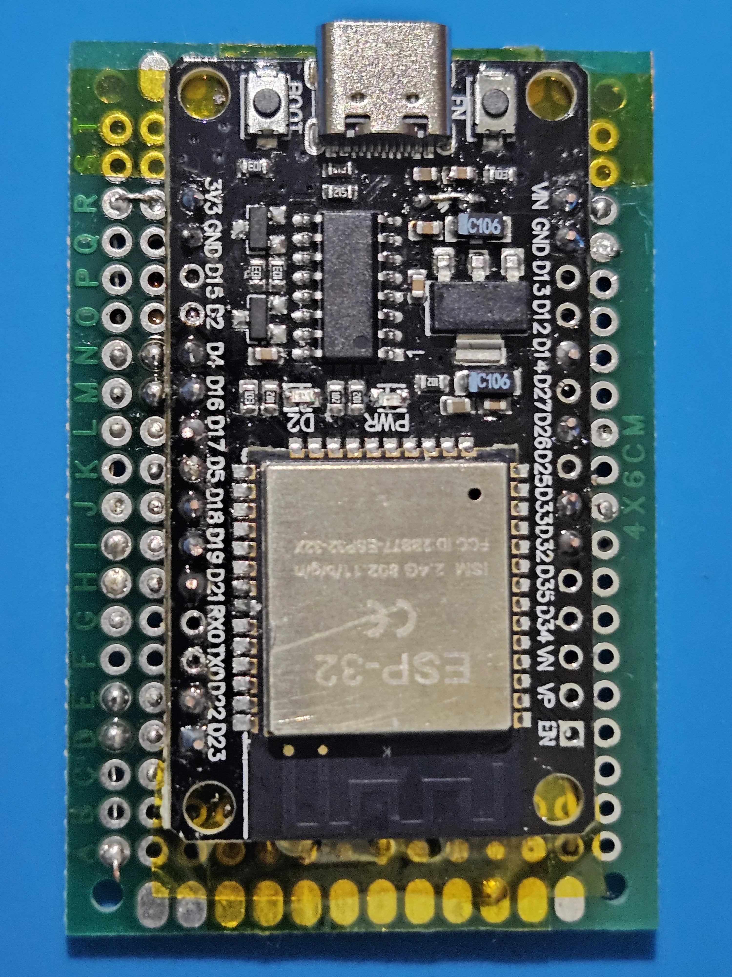 PCB top view with ESP32 mounted
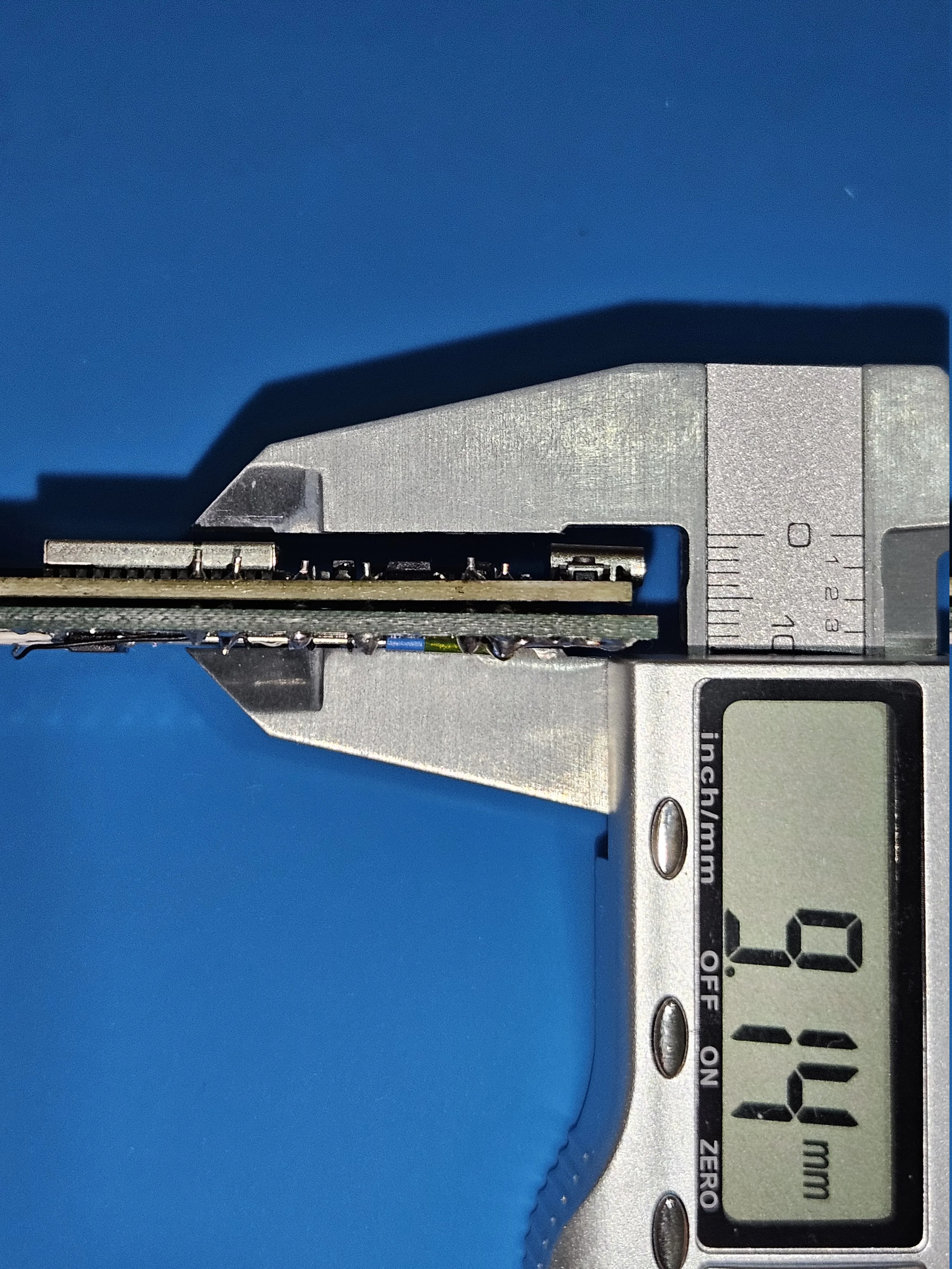
PCB Thickness Reference
The default board can fit PCBs up to 12mm thick or 8mm when using the LED strip/wire spacers. Mine was 9mm and I used spacers so it wouldn't fit by 1mm. If your PCB doesn't fit, scale and move the "BorderScale" object part in BambuStudio to achieve the thickness you prefer.
Step 2 - LED Strip Installation
Glue the LEDs flush for even light diffusion without shadows. Cut the strip for easier installation, you'll reconnect it later and control it as one continuous strip in software. Test the strip with the ESP32 before cutting to ensure all LEDs work.
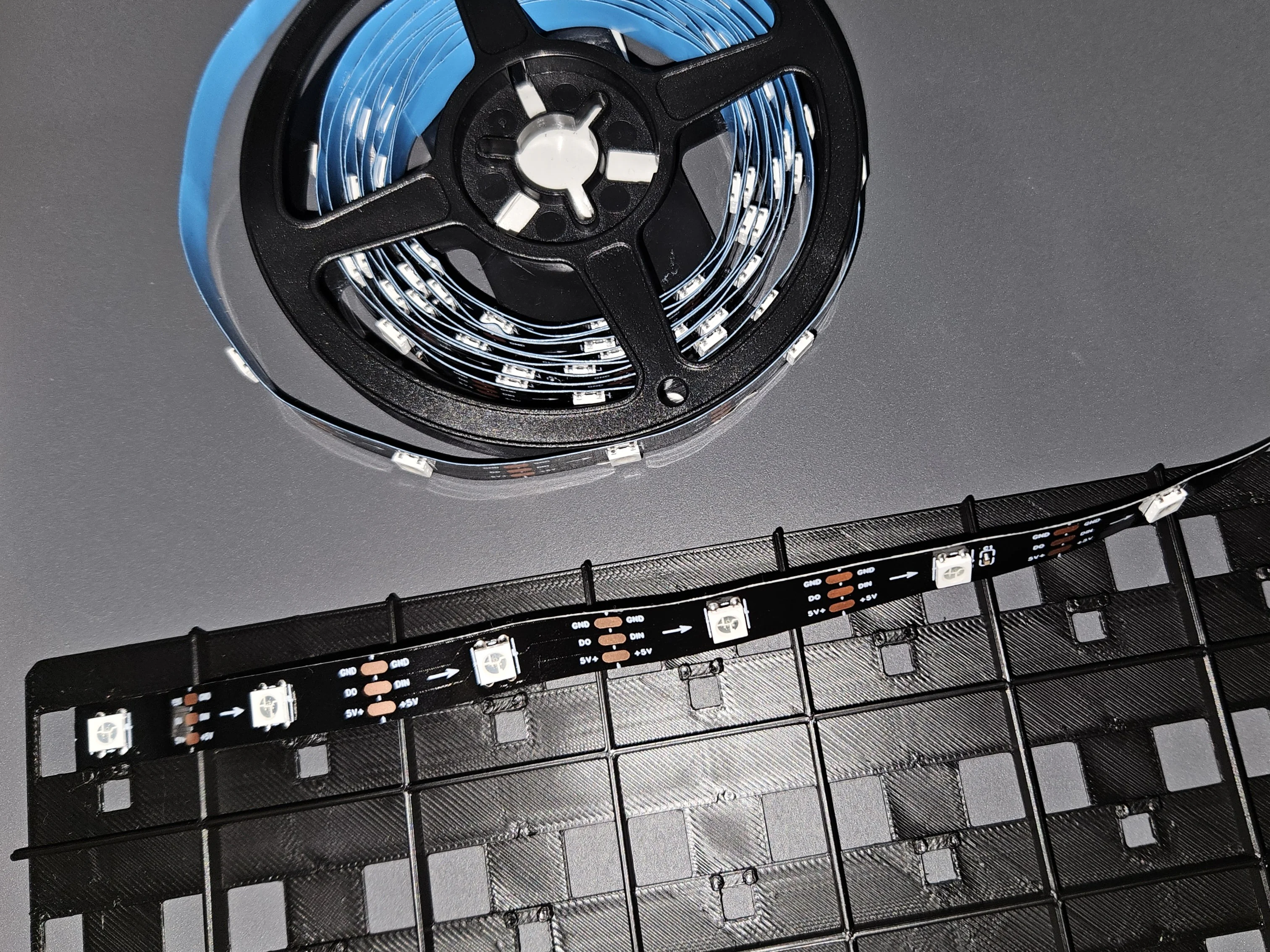
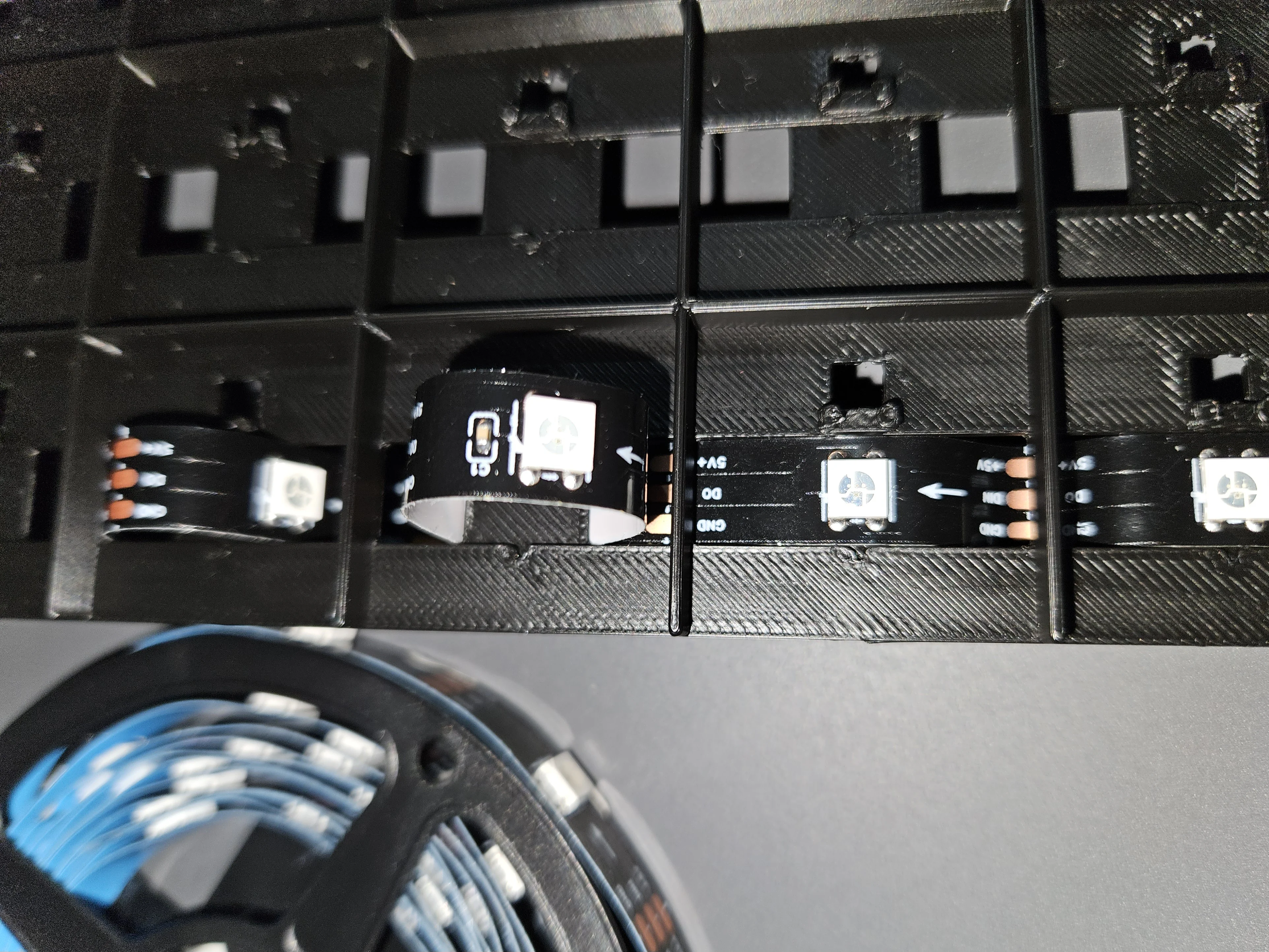
Cut the LED Strip
Cut the WS2812B LED strip at every 8th LED along the marked cut lines. You'll have 8 segments of 8 LEDs each (64 LEDs total)
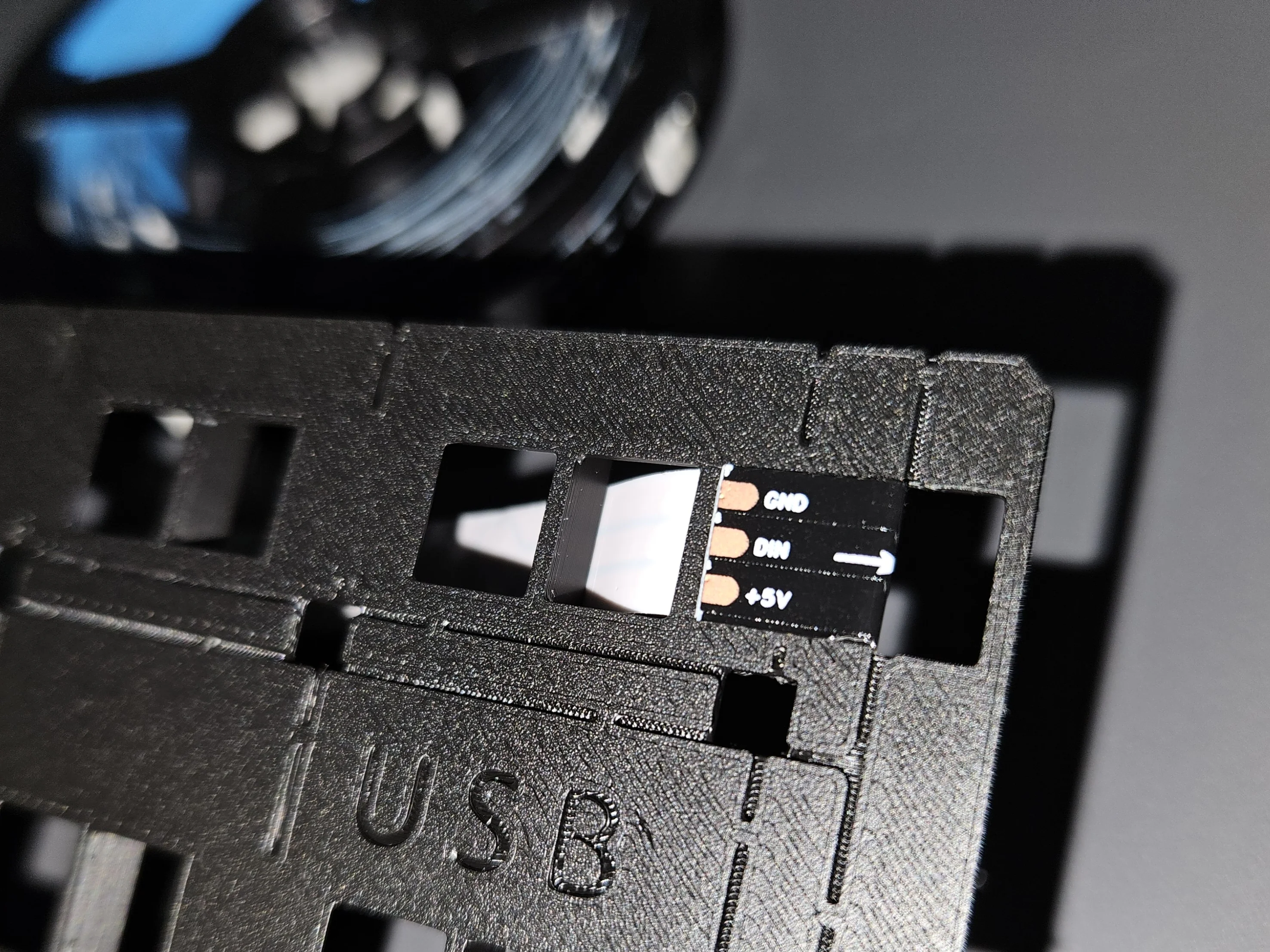
Glue Strip End
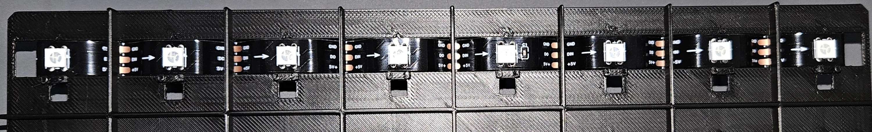
Remove the bi-adhesive backing and glue the first LED into position: there is a notch in the plastic PCB indicating where the LED center should be placed. Start from one corner and make sure the data arrow direction is correct.
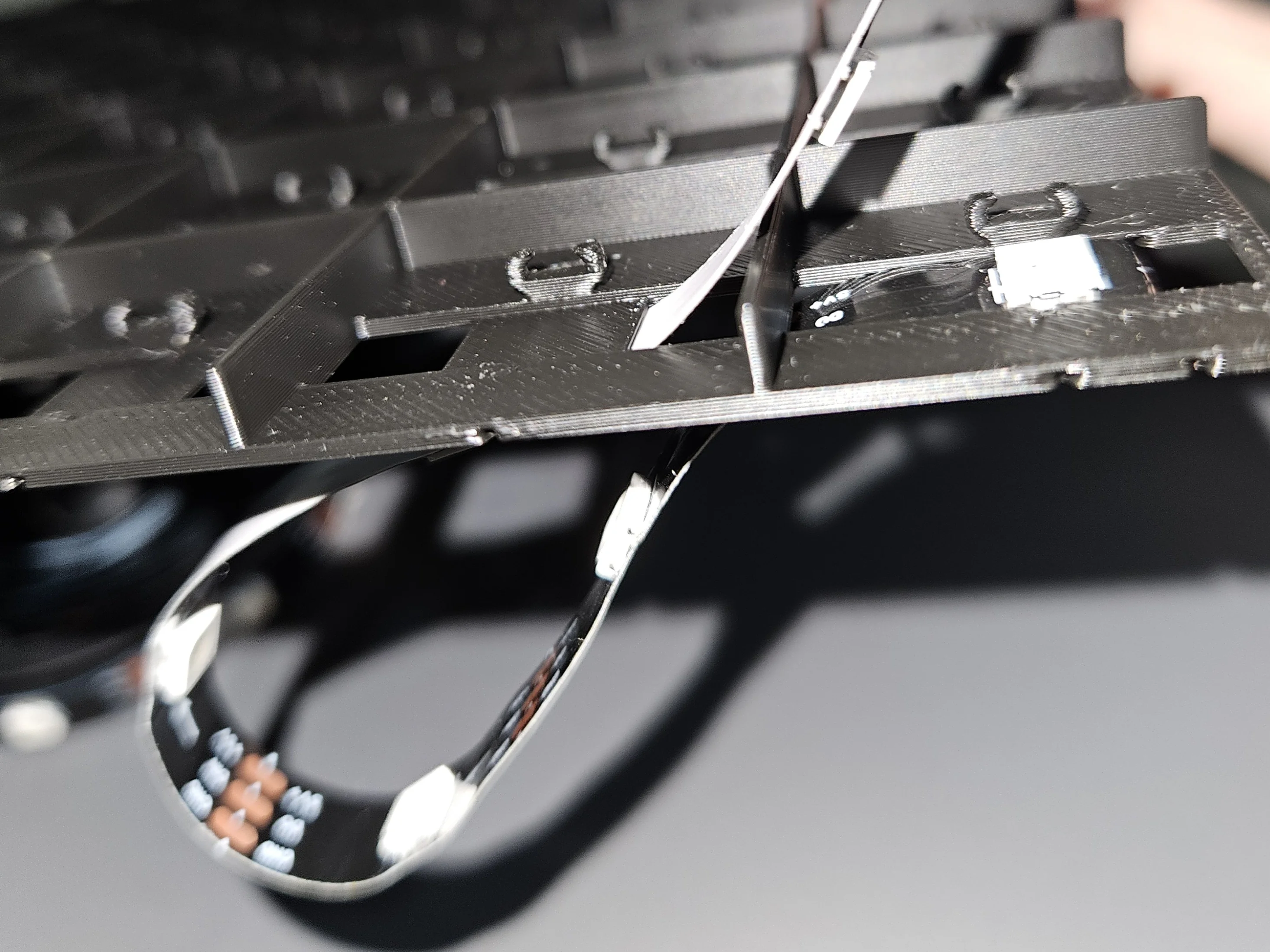
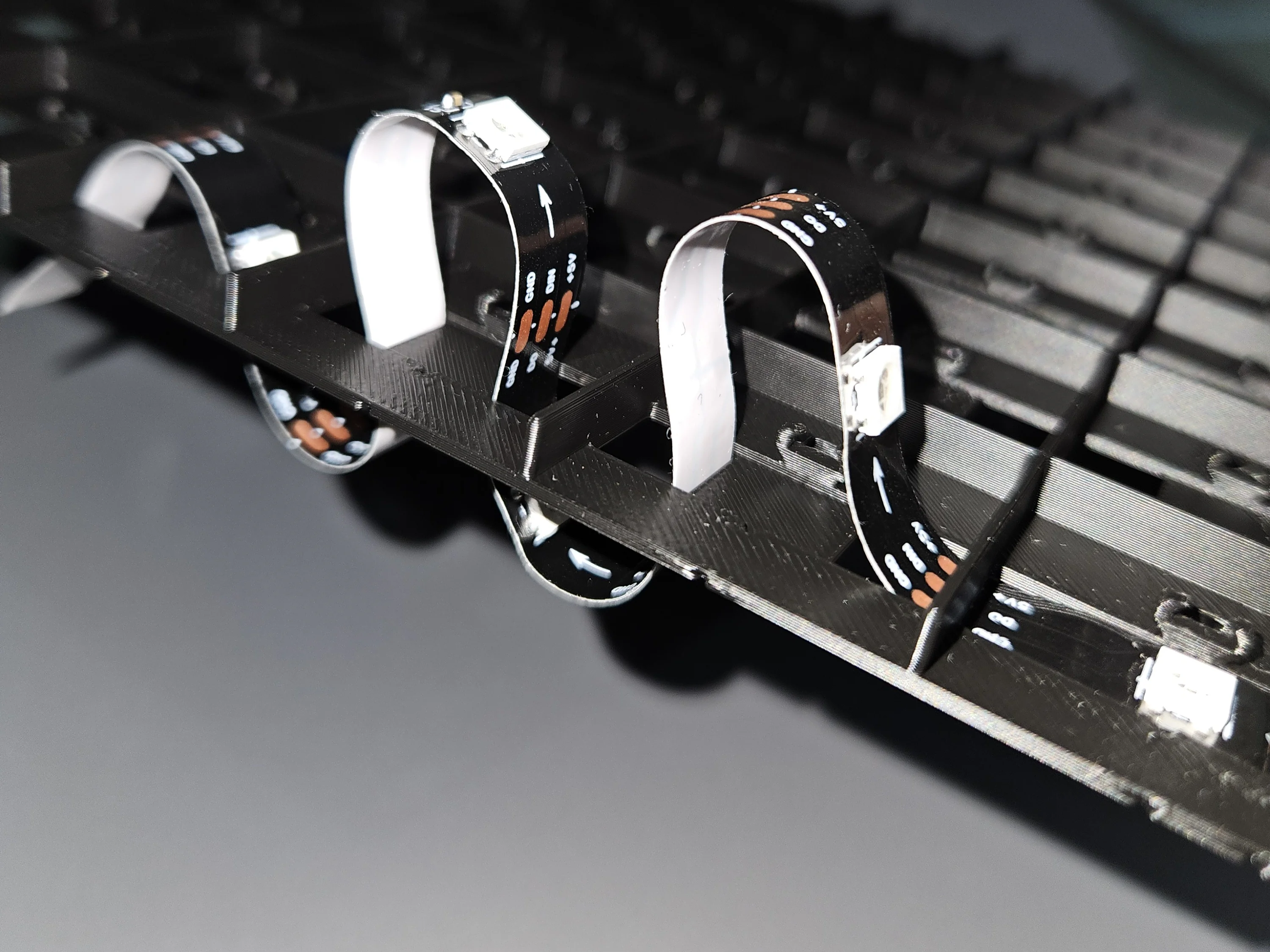
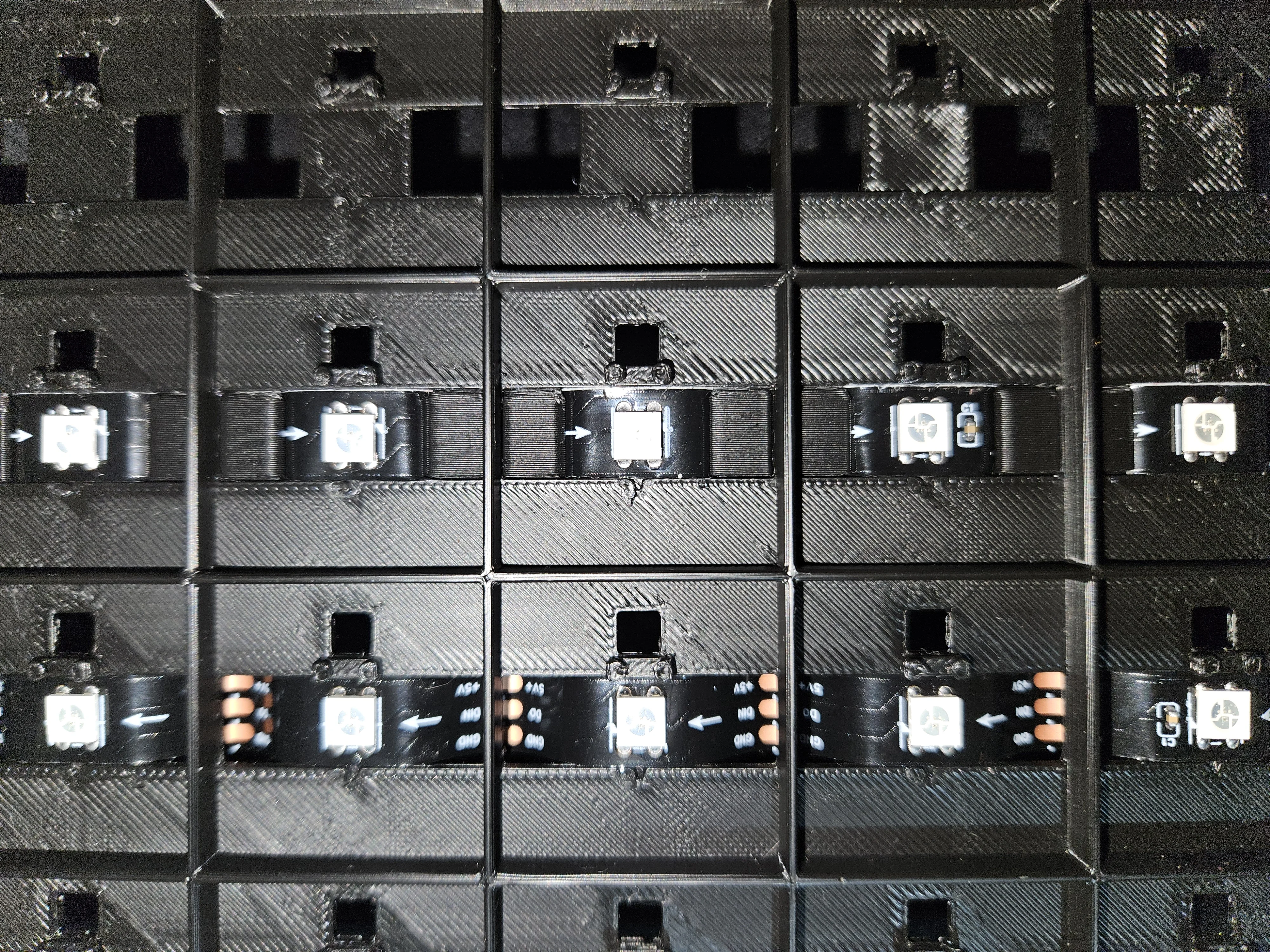
Serpentine Routing
Route the strips in a serpentine (zig-zag) pattern - each row reverses direction (critical for correct LED data signal flow). If you want to add spacers, now's the time to insert them between the strip and the board surface before pushing down on the glue.
Strip Installation Complete
Front and back views of the completed LED strip installation.
 Front view
 Back view
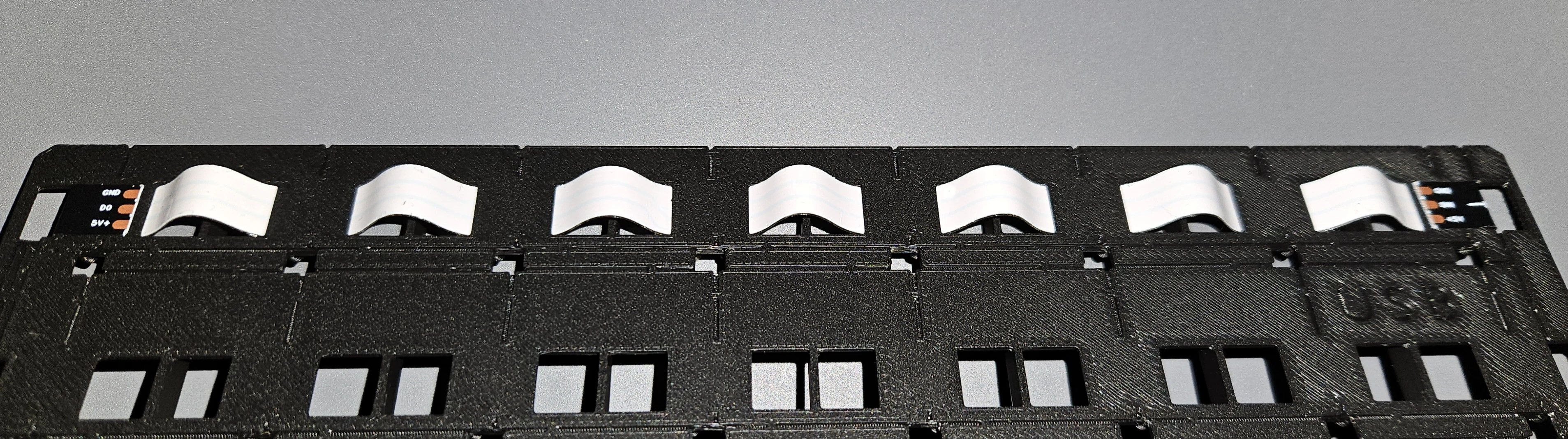
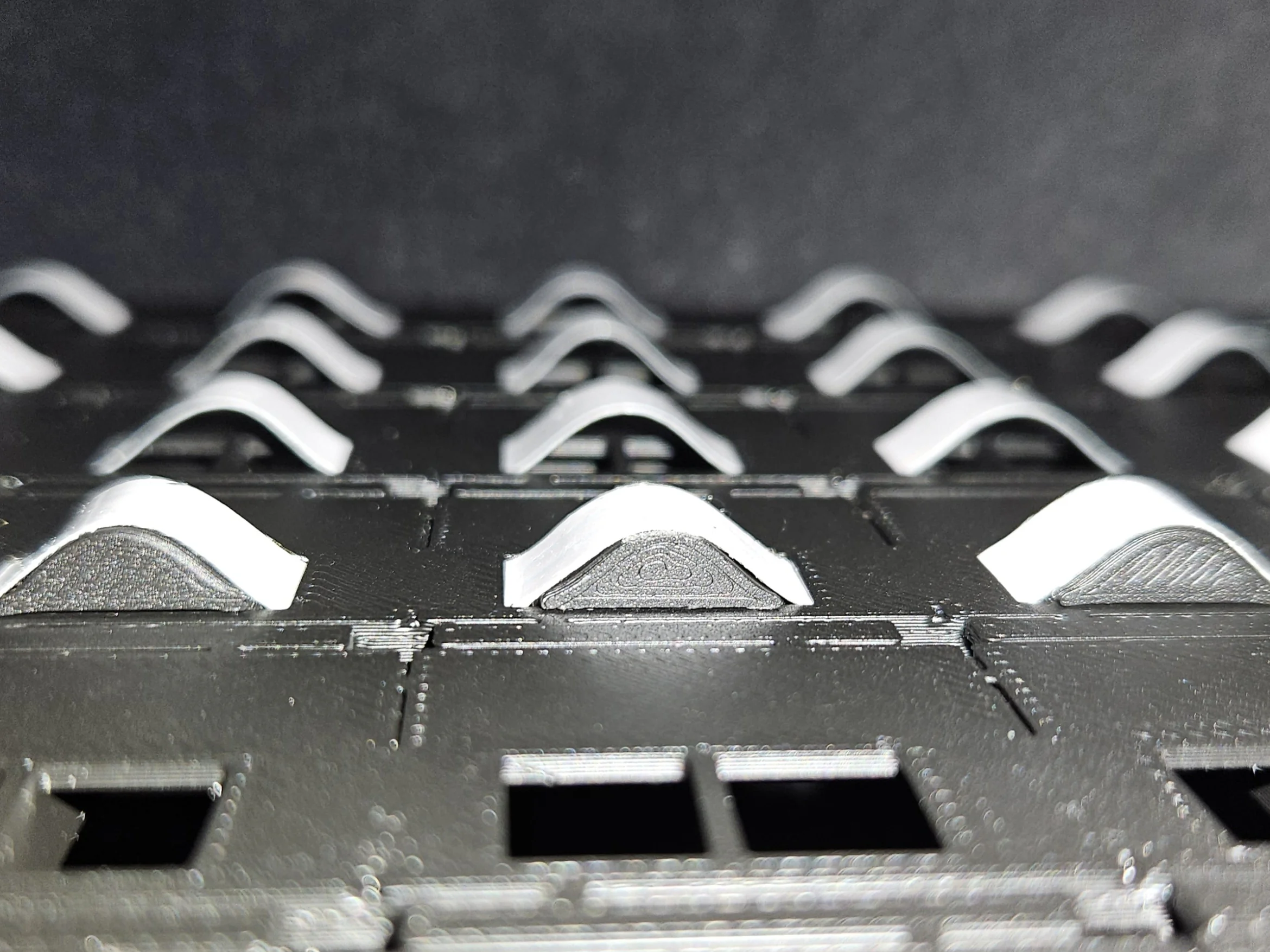
With Spacers Installed
The strip will have some slack which might cause accidental ungluing, to prevent it you can add spacers. Make sure your ESP32 PCB is thin enough to fit under the board with them in place.
 Front with spacers
 Back with spacers
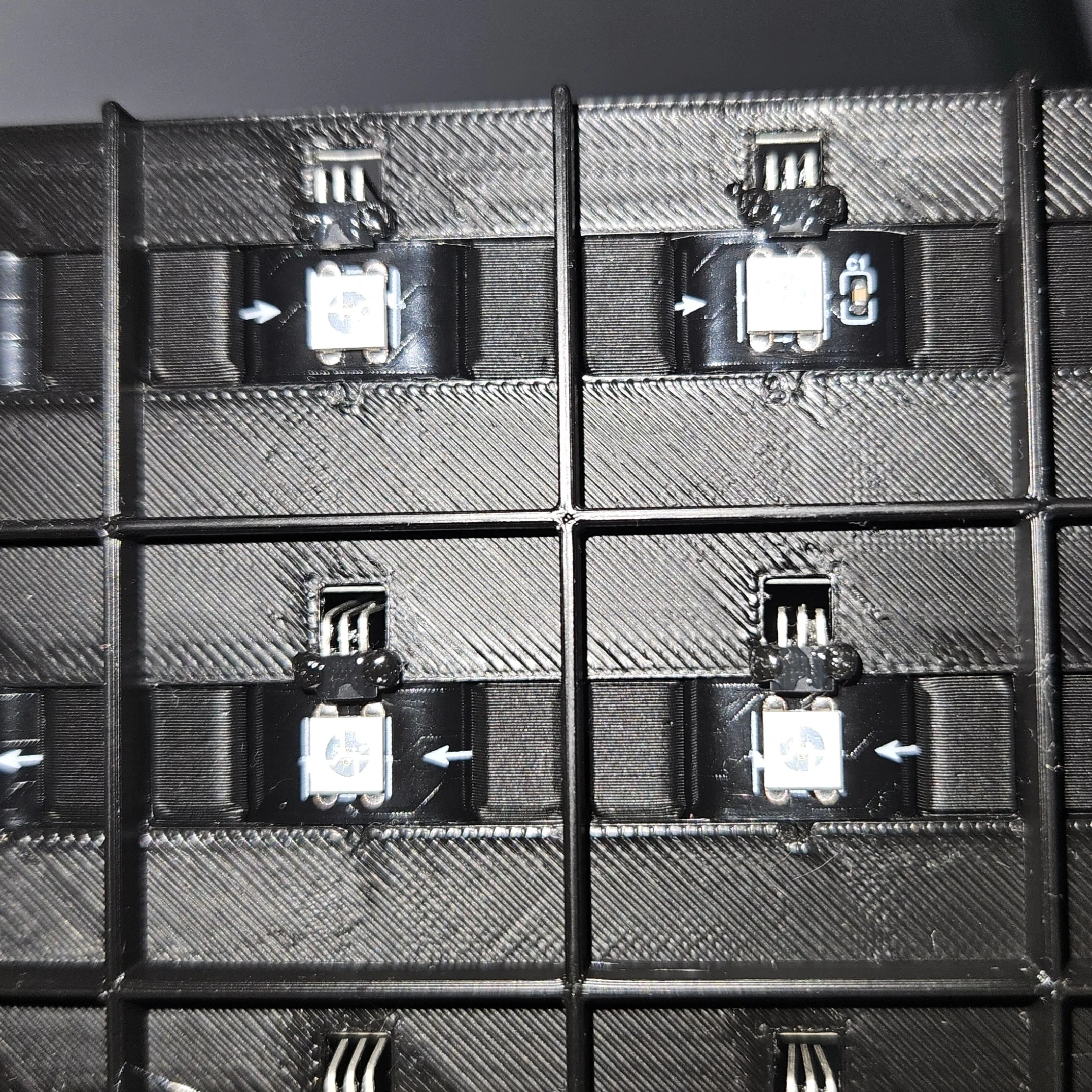
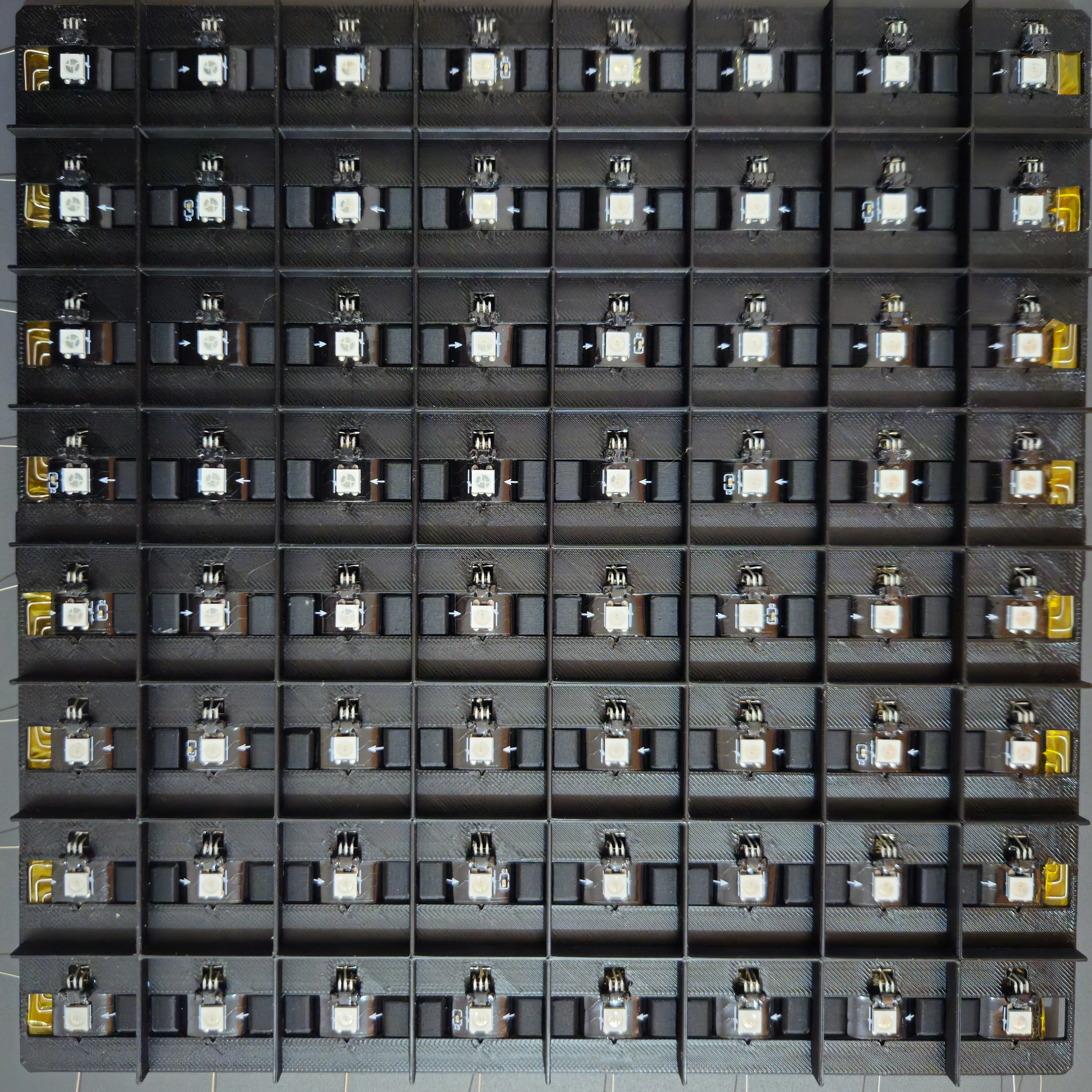
Step 3 - Sensor Placement
Install the A3144 hall-effect sensors - one per square, right next to each LED. These will detect the magnets embedded in the chess pieces.
Apply Glue on Sensor Holder
Put a small dab of glue where the sensor will sit.
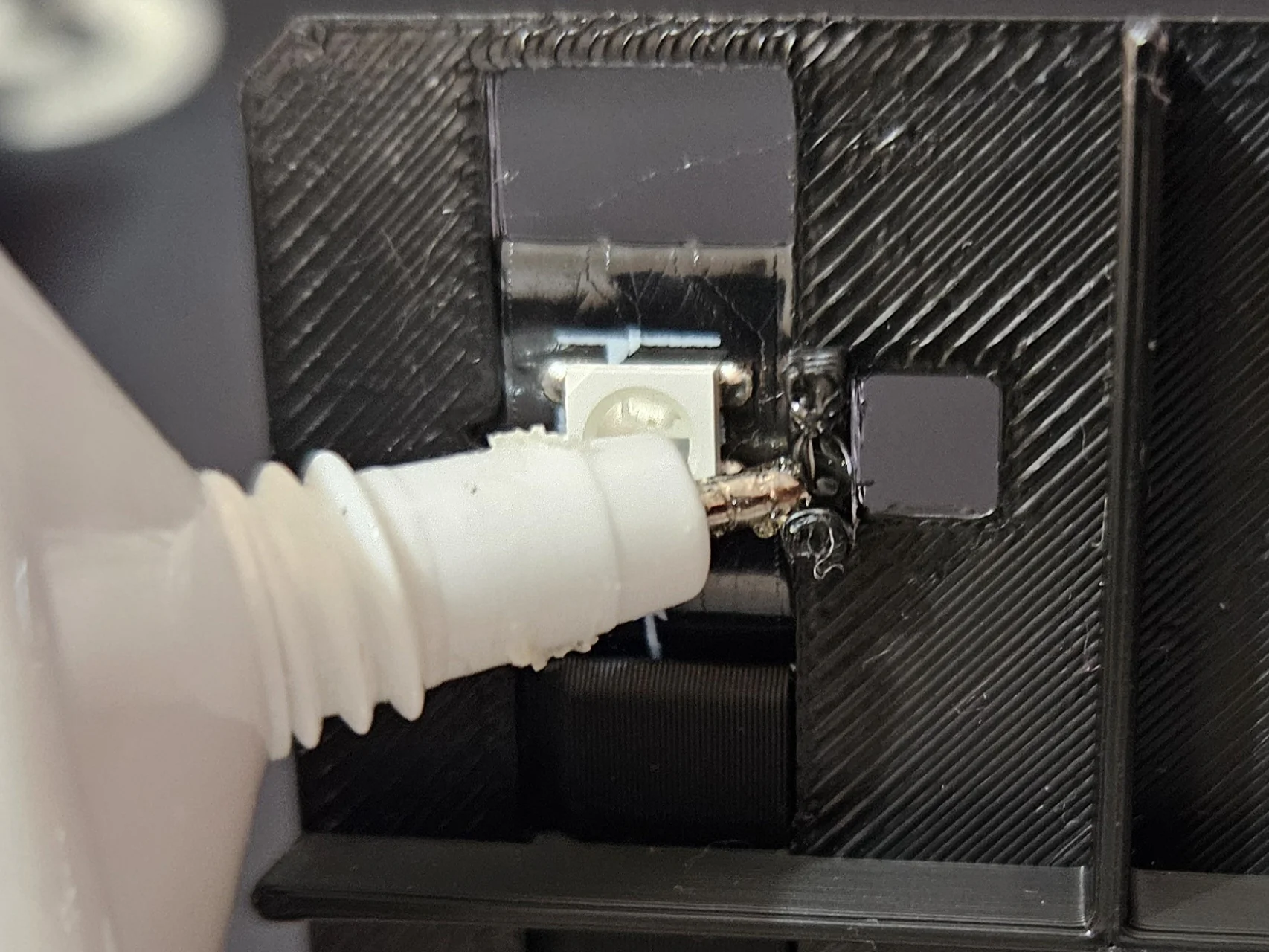
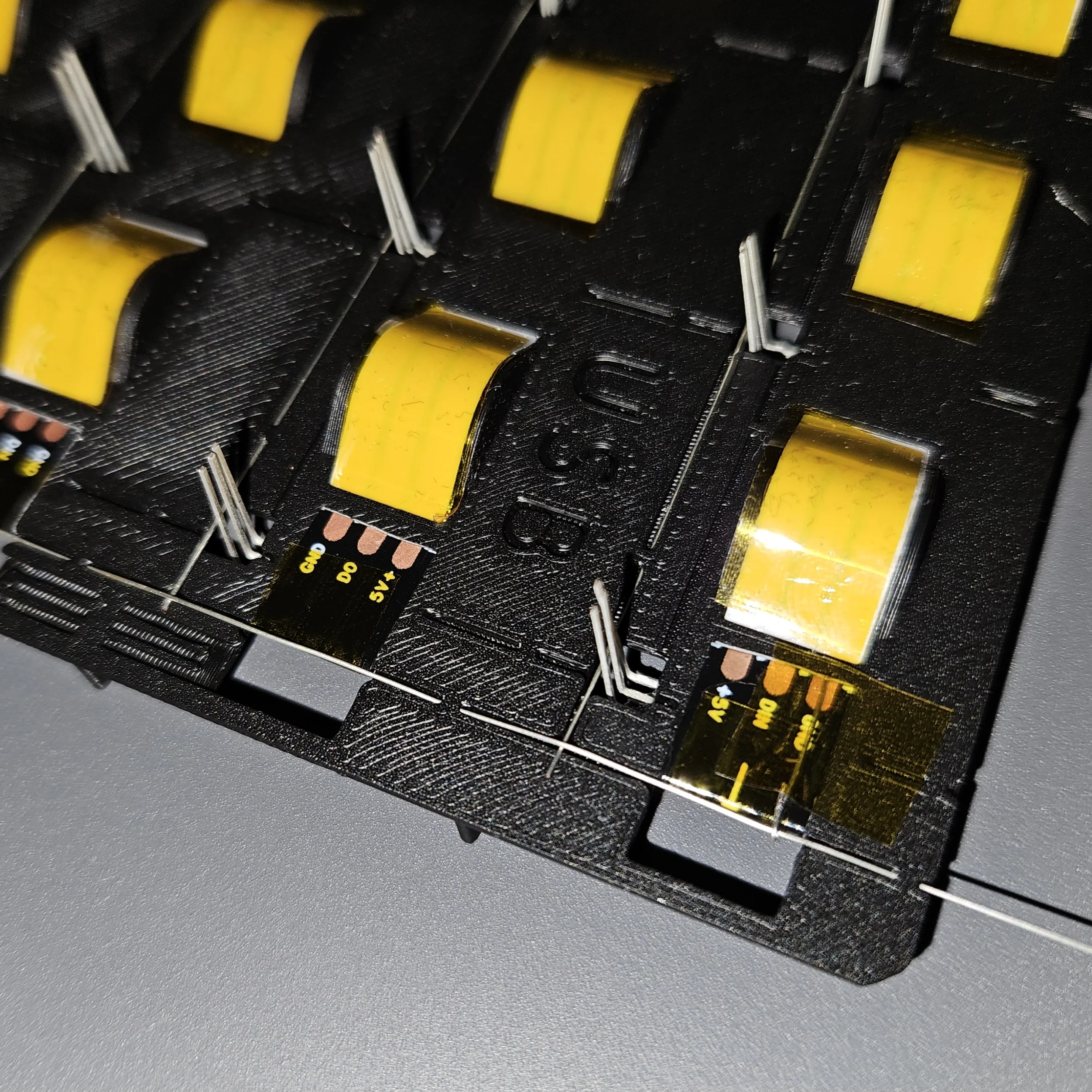
Place the Sensor
Bend the A3144 sensor pins 90 degrees and place it on the holder as shown in the picture, pins should stick out the back.
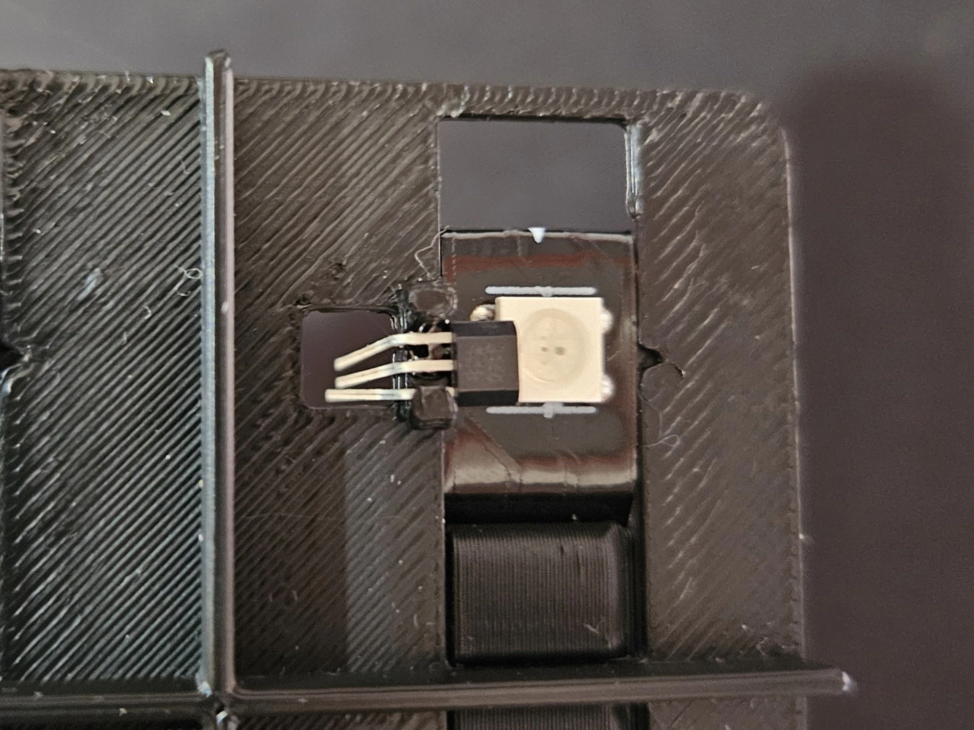
Push Sensor into Glue
Press the sensor into the holder and glue.
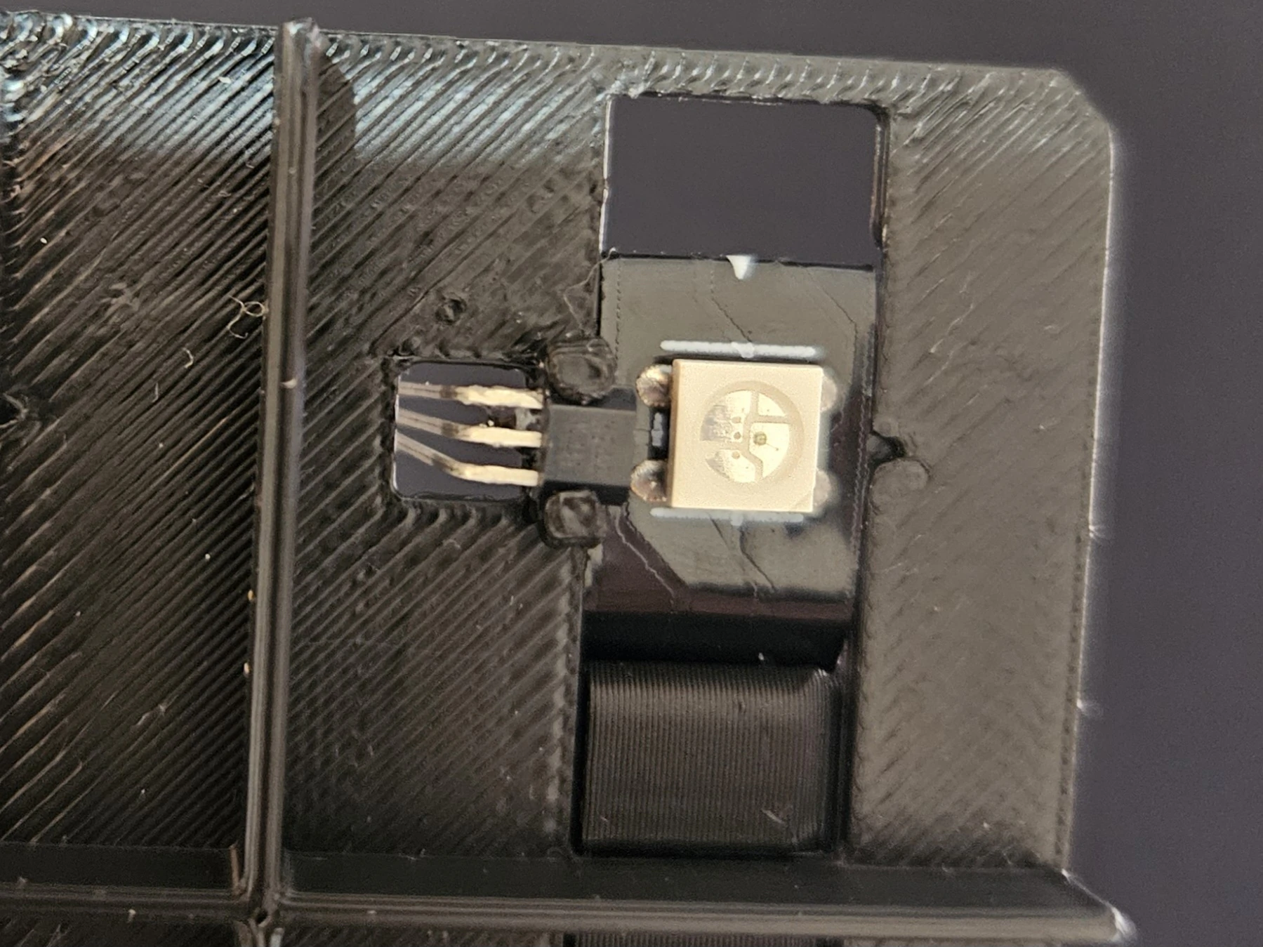
Reinforce with More Glue
Add more glue around the sensor to secure it firmly, you don't want it moving around when you start soldering wires to it.
Step 4 - Wiring: Ground (GND)
Run ground wires through the board's wire guides, connecting sensor GND pins and LED strip GND together. This creates a common ground reference for the entire board, which we then can easily insulate to avoid shorts with other wires we add later.
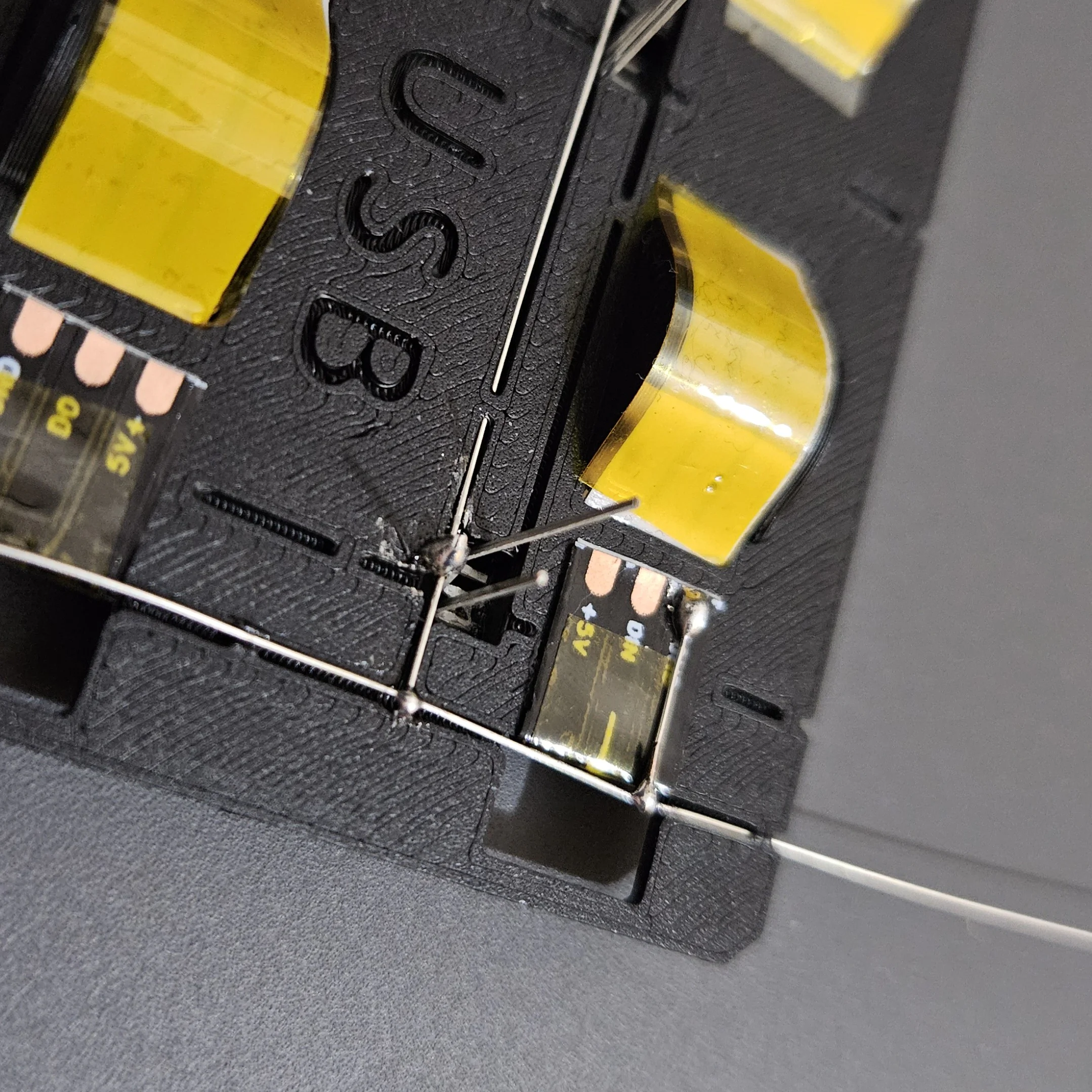
Pass GND Wires Through Guides
Thread the ground wires through the built-in wire guides on the board. These keep the wiring tidy and prevent shorts.
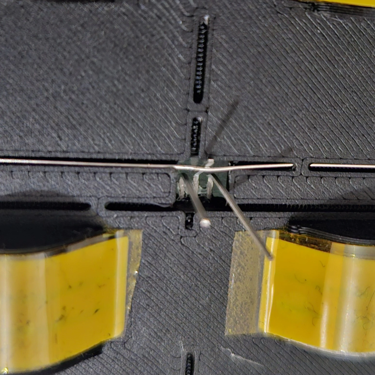
Move Sensor GND Over Pin
Bend the GND wires over the sensor's GND pins. This creates distance from the plastic and forces the wire to stay tight and close to the pin, making it easier to solder. Cut the sensor GND pins flush to keep things tidy.
LED Strip GND Connection
Connect the LED strip GND pads to the same ground bus.
Solder LED Strip GND
Solder GND wires to the LED strip GND pads.
Solder Sensor GND
Solder the ground wires to each sensor's GND pin.
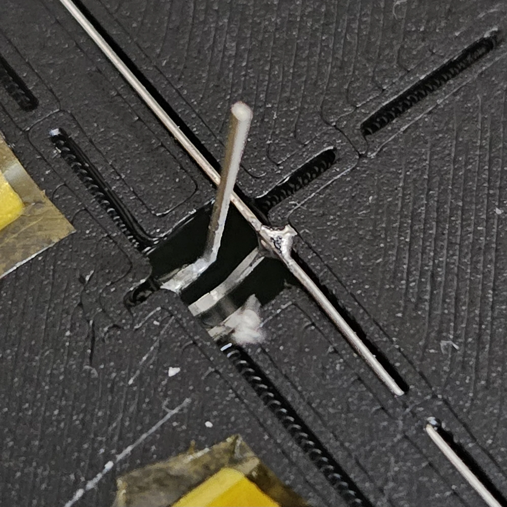
Solder GND Wires
Continue soldering all GND connections row by row until every sensor and LED strip segment shares a common ground.
 In progress
 Completed
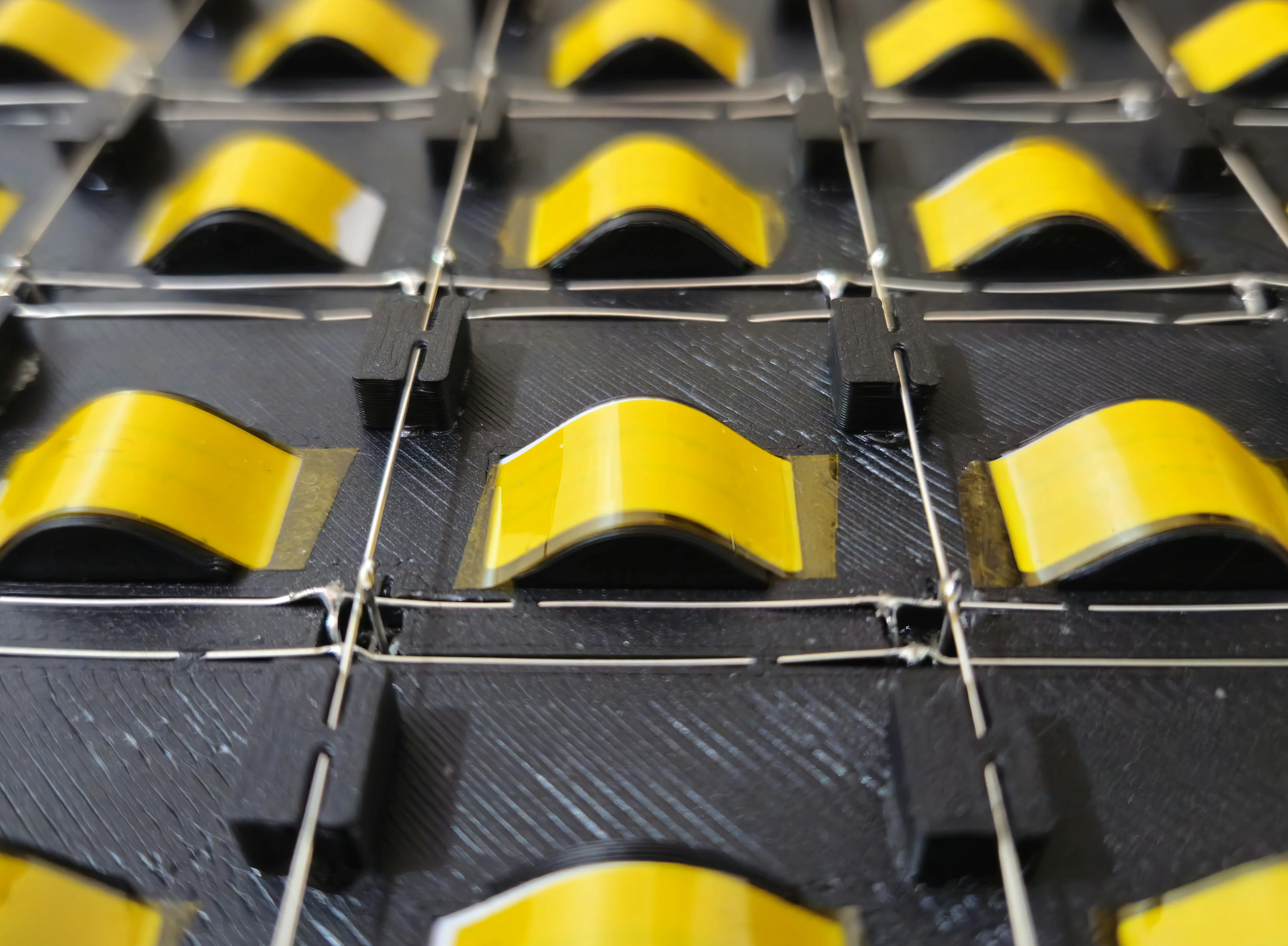
Step 5 - Wiring: LED Strip Data & Power
Connect the LED data and 5V between LED strip segments, turning the 8 segments back into one continuous strip.
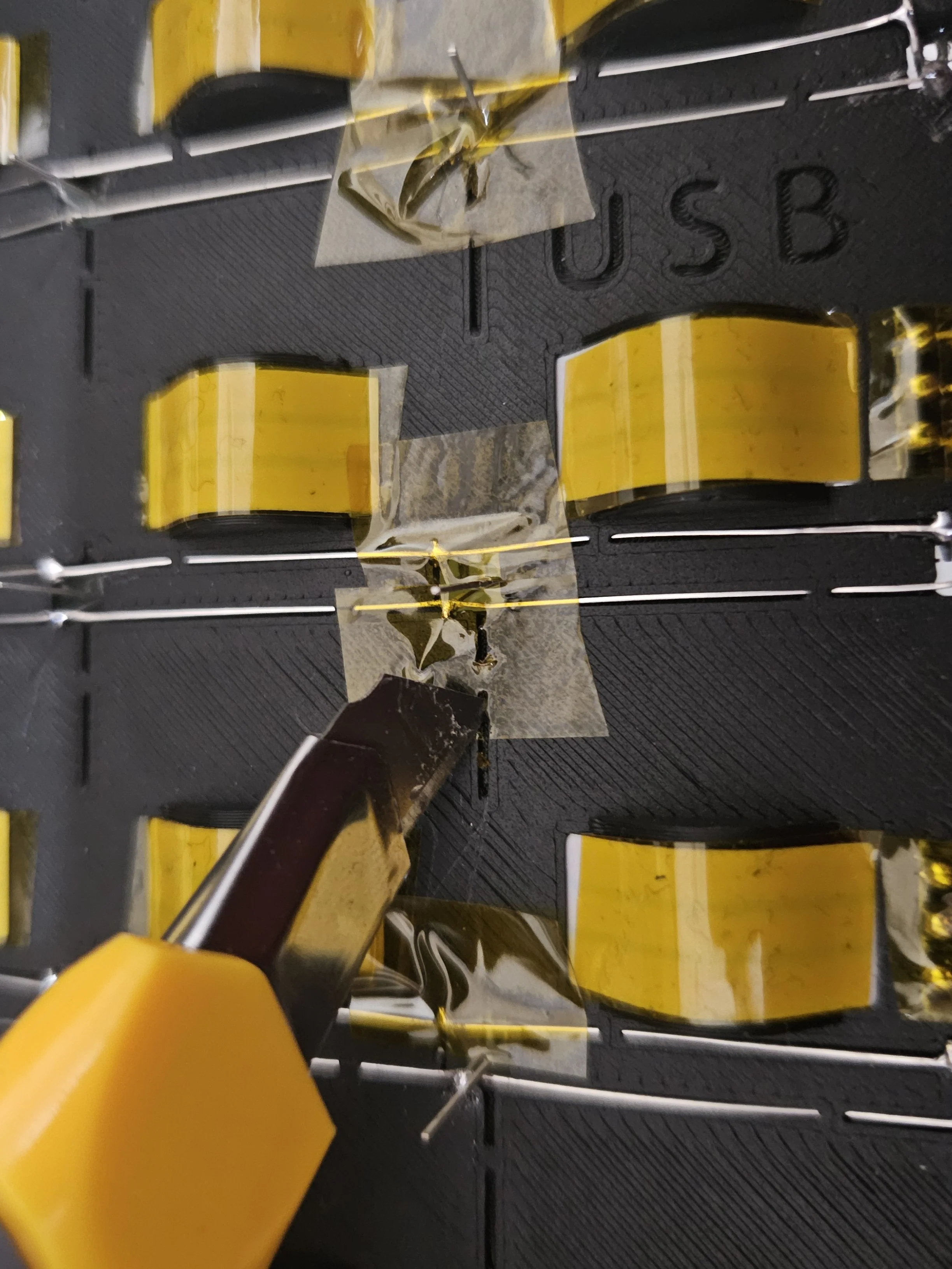
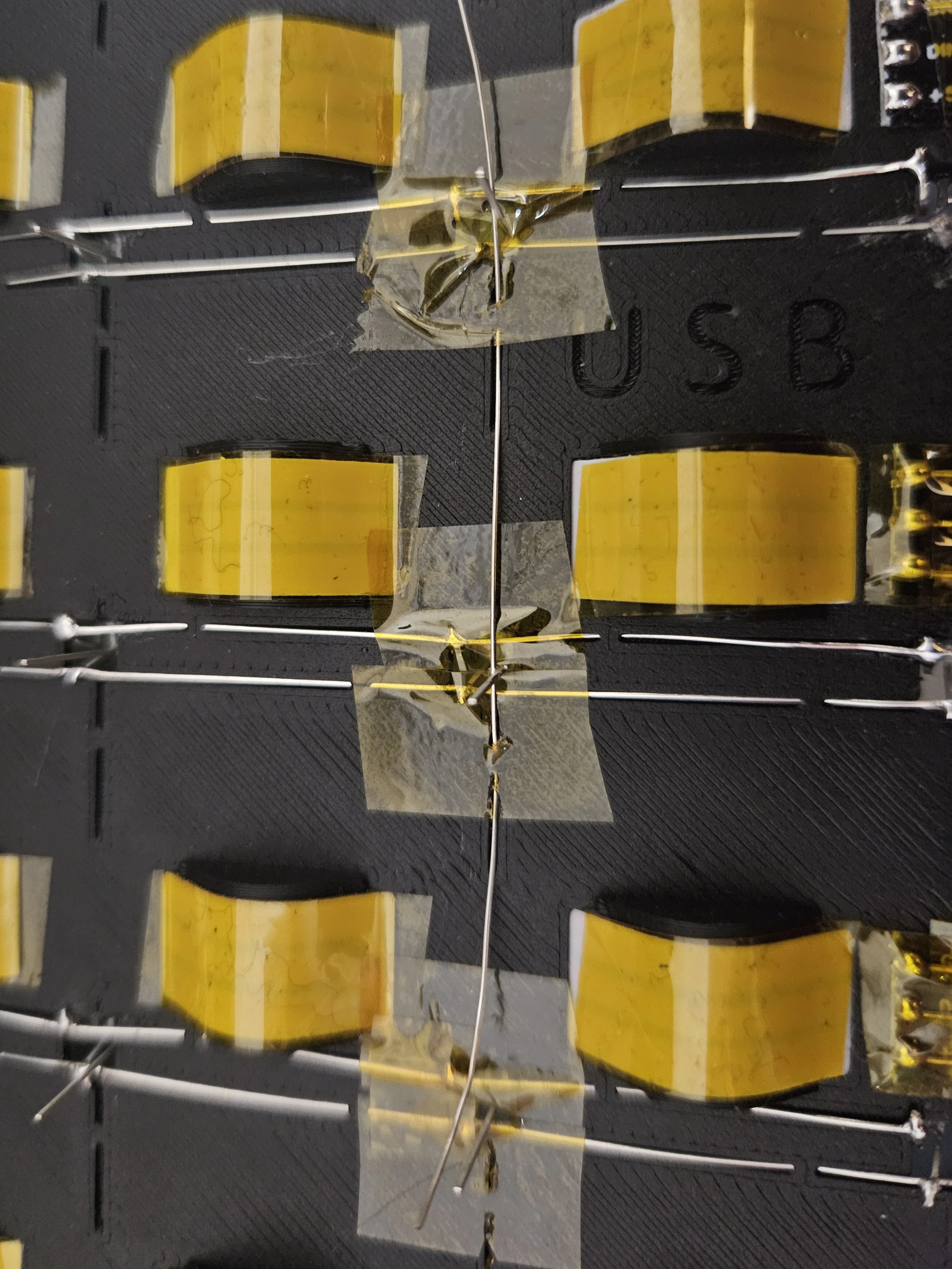
Cover GND Wires
Apply tape over the ground wires to insulate them and prevent shorts with other wires.
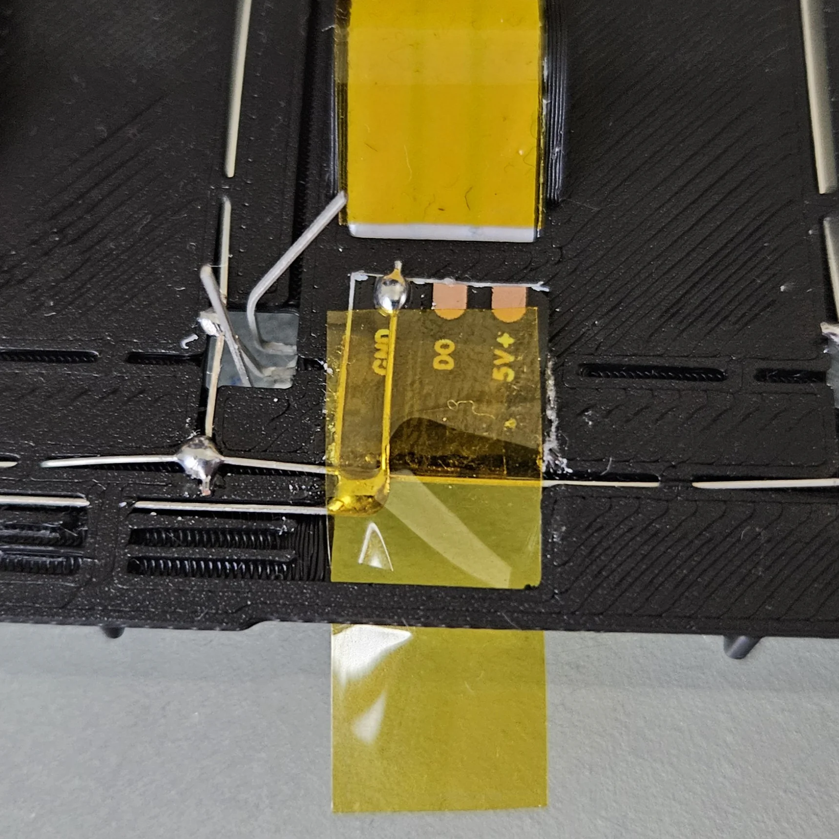
Solder All LED Strip Wires
Solder the LED data and 5V wires between each LED strip segment following the serpentine layout.
Cover All LED Strip Wires
Insulate all LED strip connections with tape to prevent shorts.
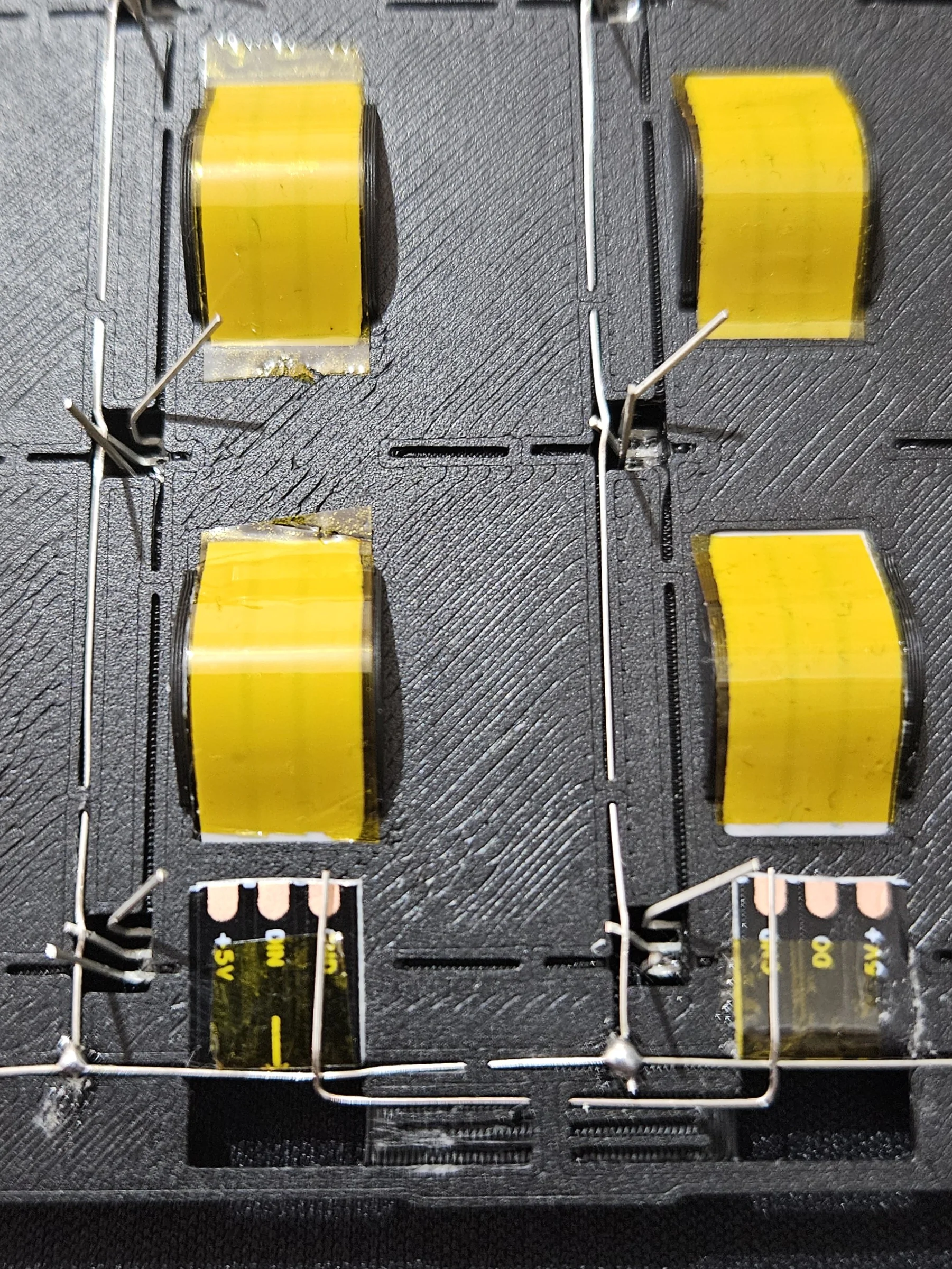
Step 6 - Wiring: Sensor Row Wires
Connect the sensor output pins in each row. All 8 sensors in a row share one output wire that goes to an ESP32 GPIO pin.
Pass Row Wires
Thread row wires through the board as you did for the GND wires, connecting each sensor's output pin in the same row. I melted some PLA with my soldering iron over the wires to secure them in place.
Solder Row Wires
Solder each row wire to the output pin of every sensor in that row. Each row goes to a different ESP32 GPIO pin.
 In progress
 Completed
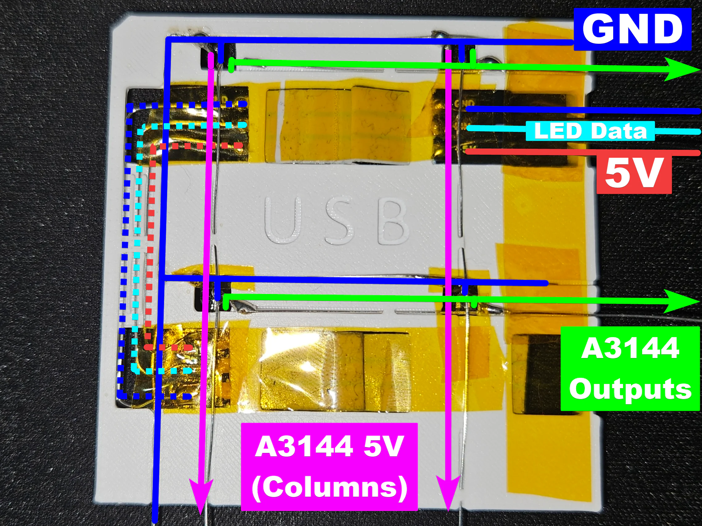
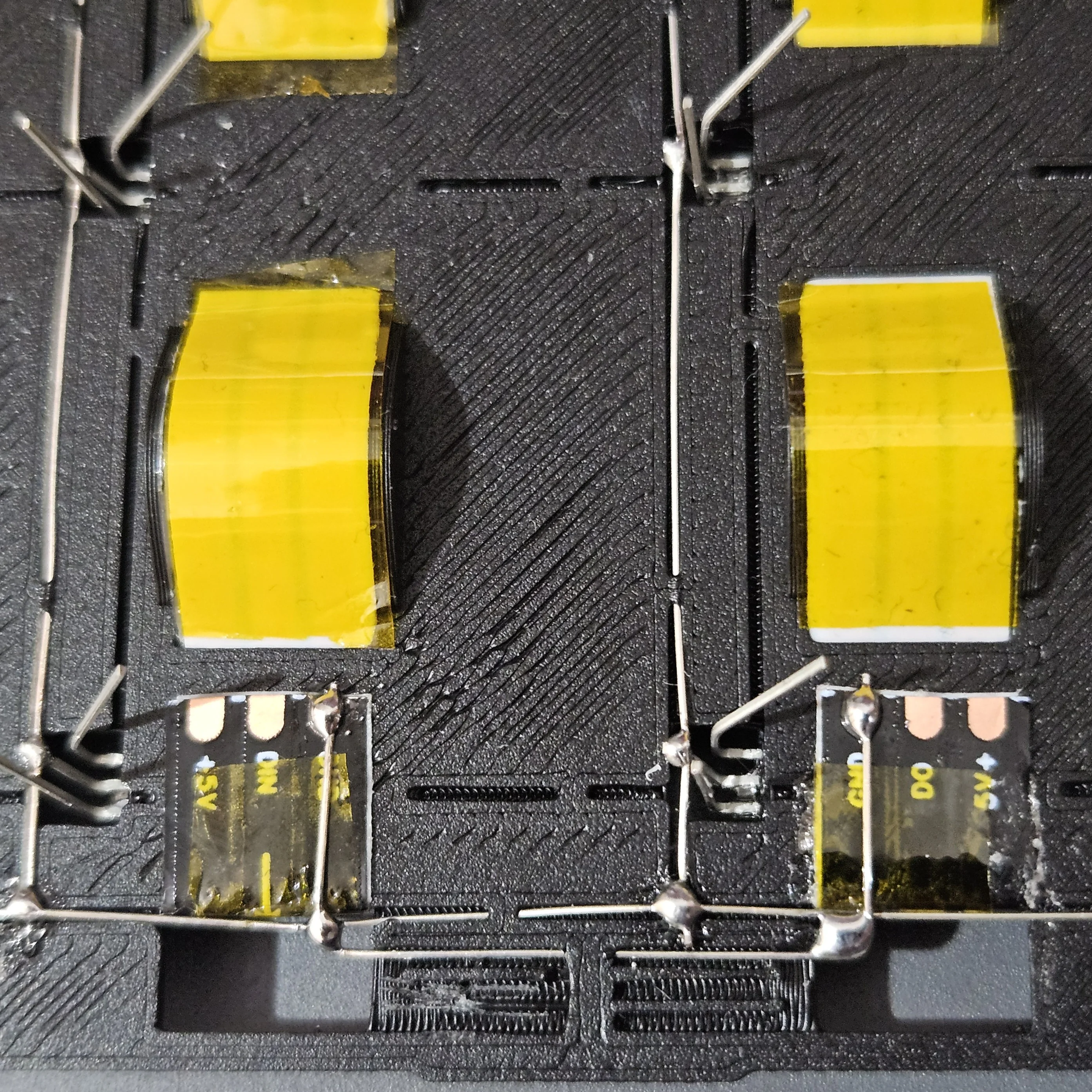
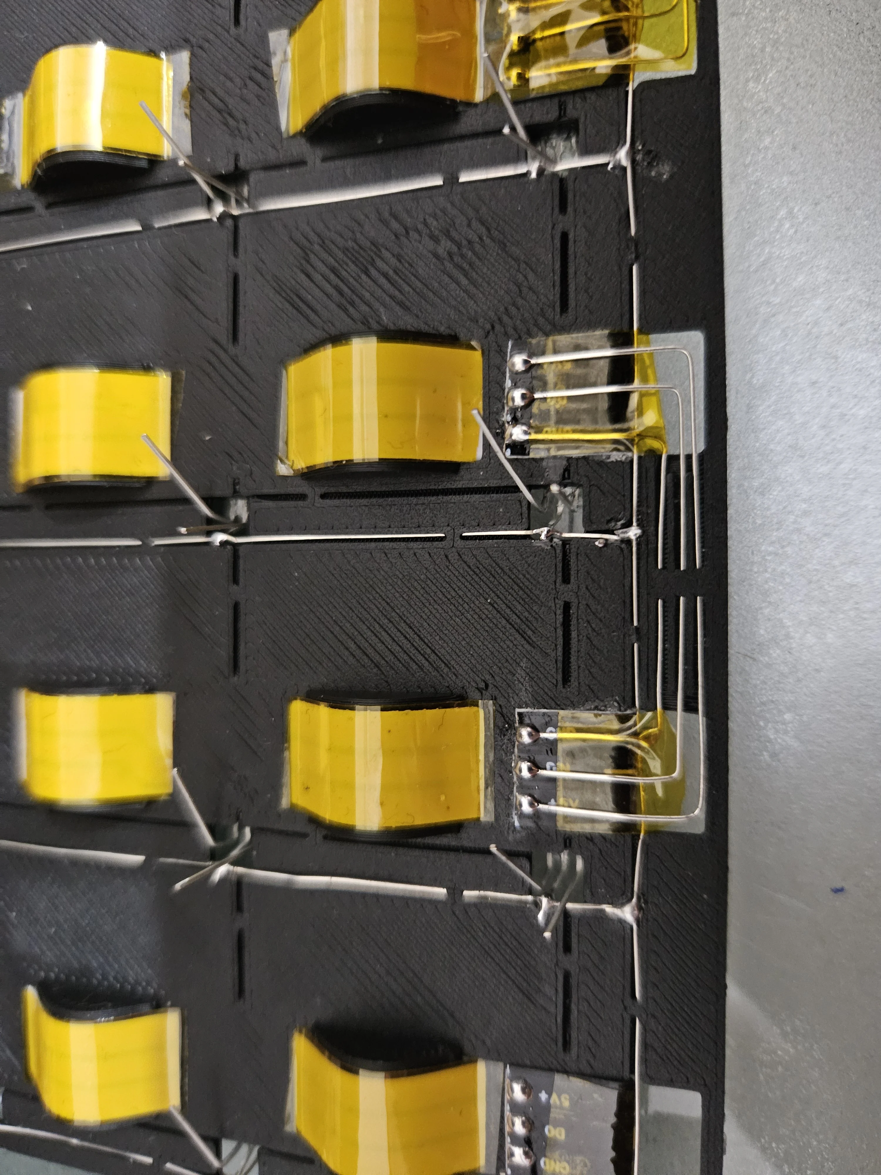
Step 7 - Wiring: Sensor 5V (Column Power)
Connect each column's sensor VCC (5V) pins. These are driven by PNP transistors controlled by the shift register - only one column is powered at a time during scanning.
Pass 5V Wires - Method 1
First method: route the 5V wires through the wire guides along each column. Tape is required to insulate the 5V wires from the GND/row wires.
 Routing
 Completed
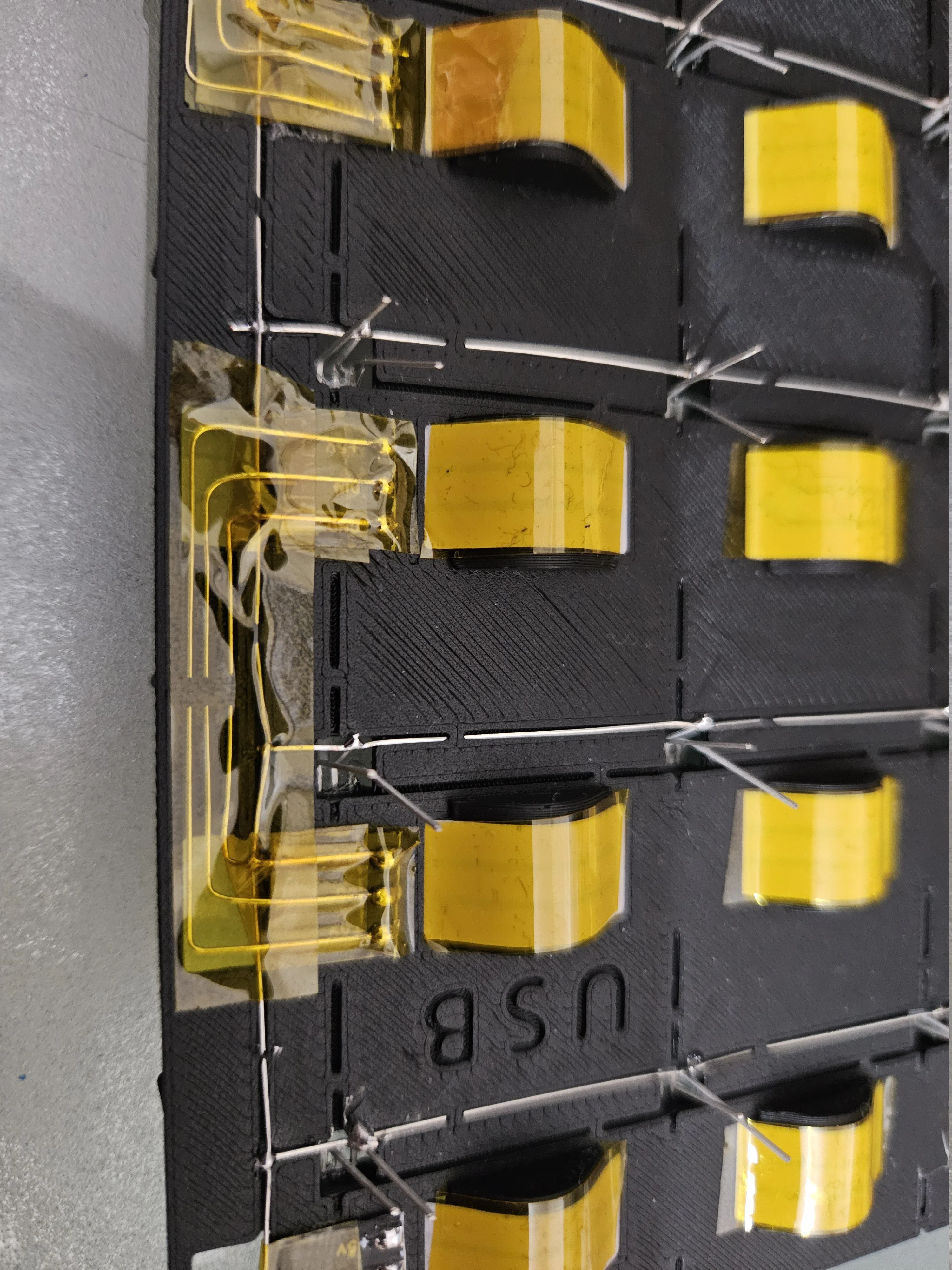
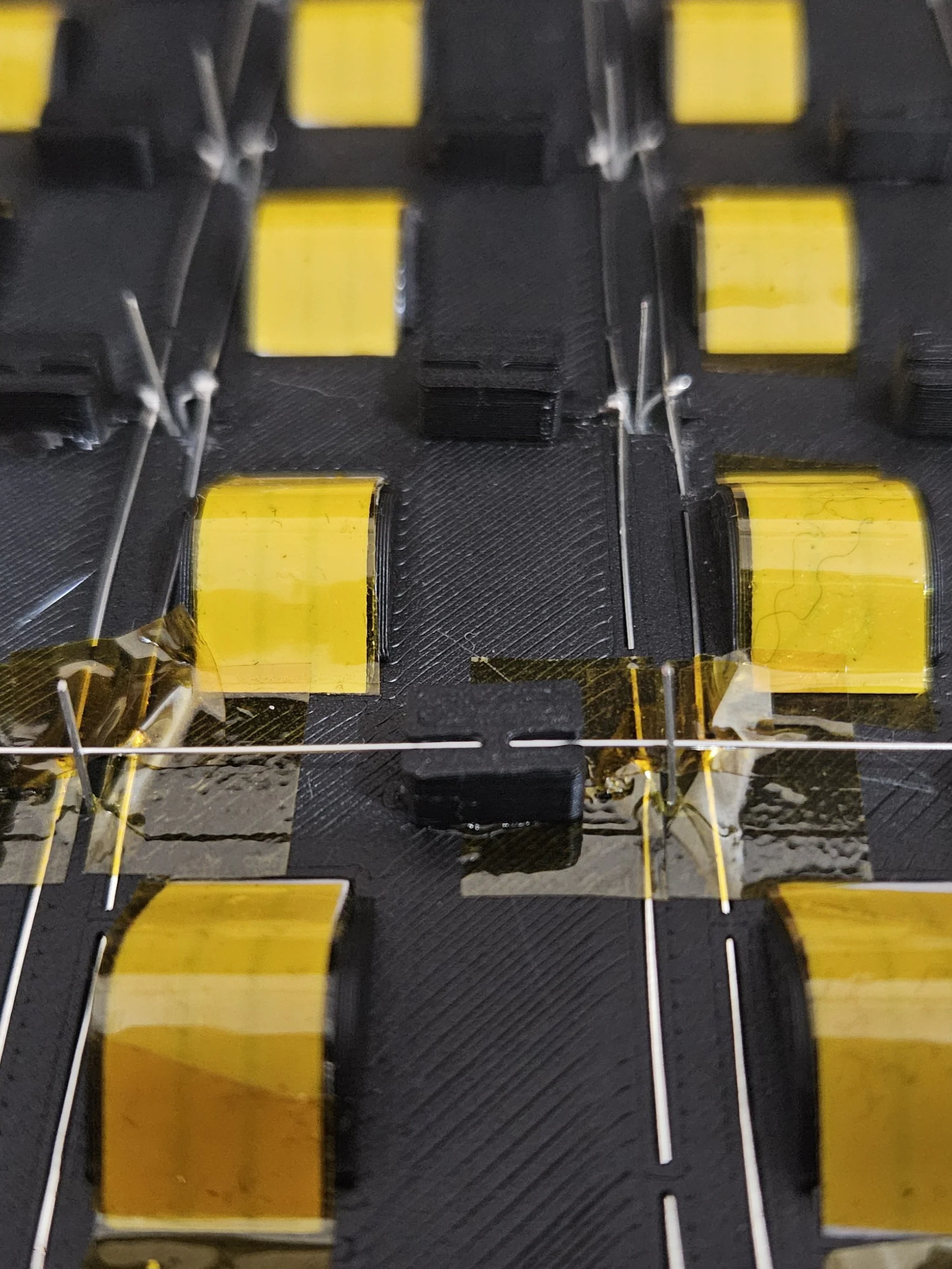
Pass 5V Wires - Method 2 (Alternative)
Alternative routing method for the 5V column wires - choose whichever you prefer. This spacer requires a thin ESP32 PCB to fit under the board, but allows easier wire routing on top of other GND/row wires, avoiding the need of tape to prevent shorts.
Cut Extra Pin Length
Trim the excess sensor pin length with flush cutters to keep things tidy and prevent shorts.
 Before cutting
 After cutting
Solder 5V Connections
Solder the 5V wires to each sensor's VCC pin along the column. Each column wire will connect back to a transistor on the PCB (or to the shift register outputs if not using transistors)
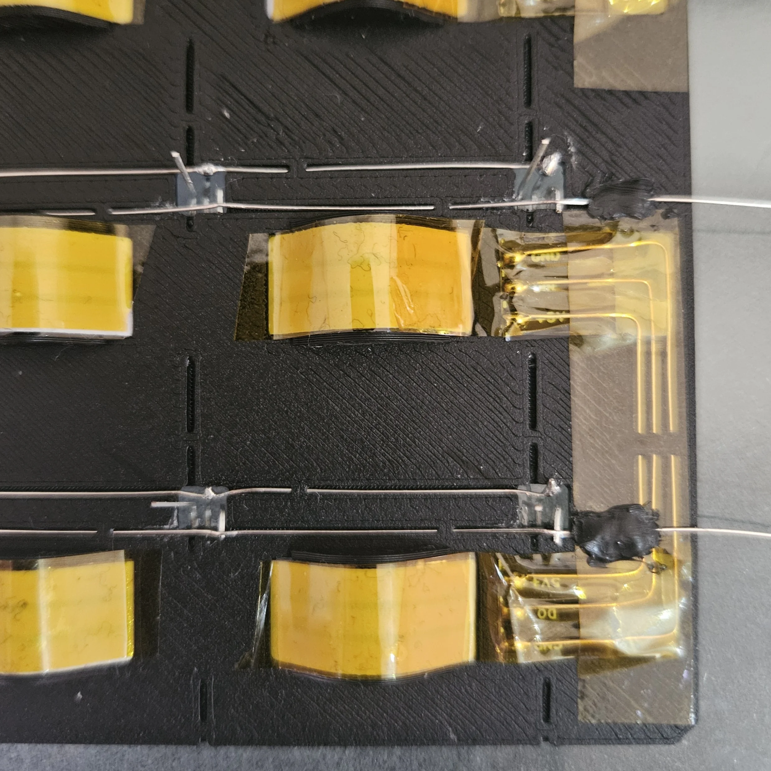
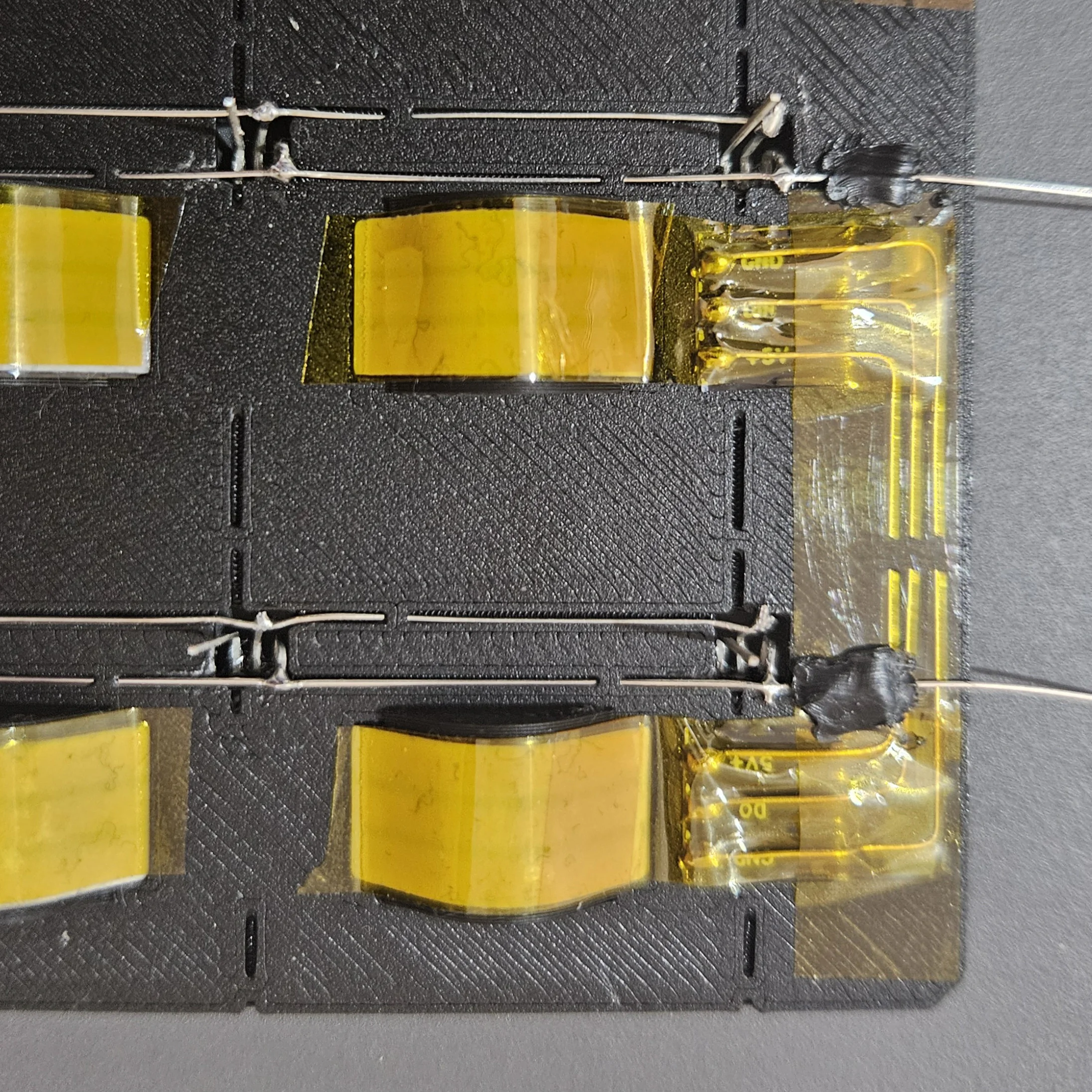
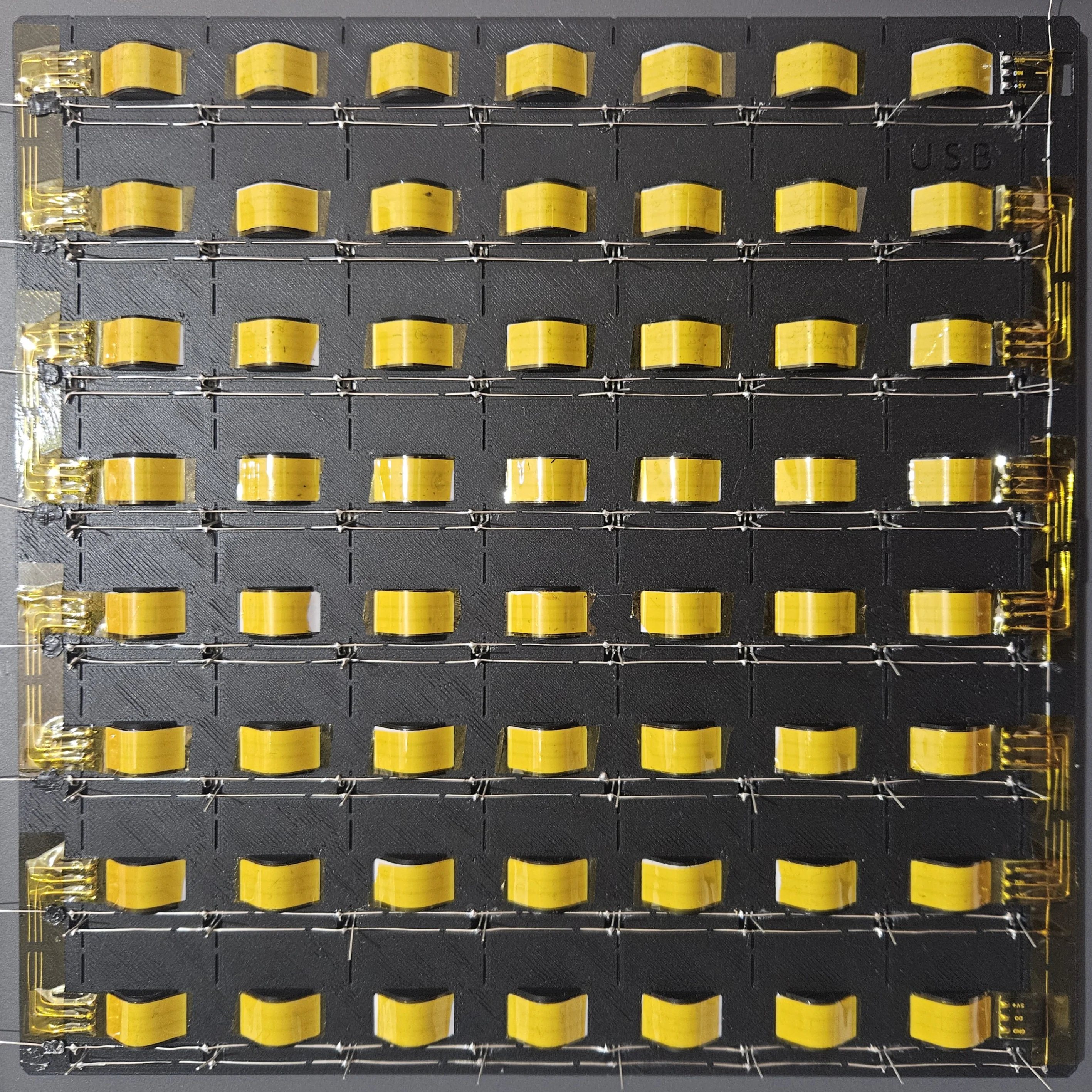
Step 8 - Plastic PCB Complete!
The board's sensor grid and LED array are now fully wired. Here's what the completed assembly looks like from different angles.
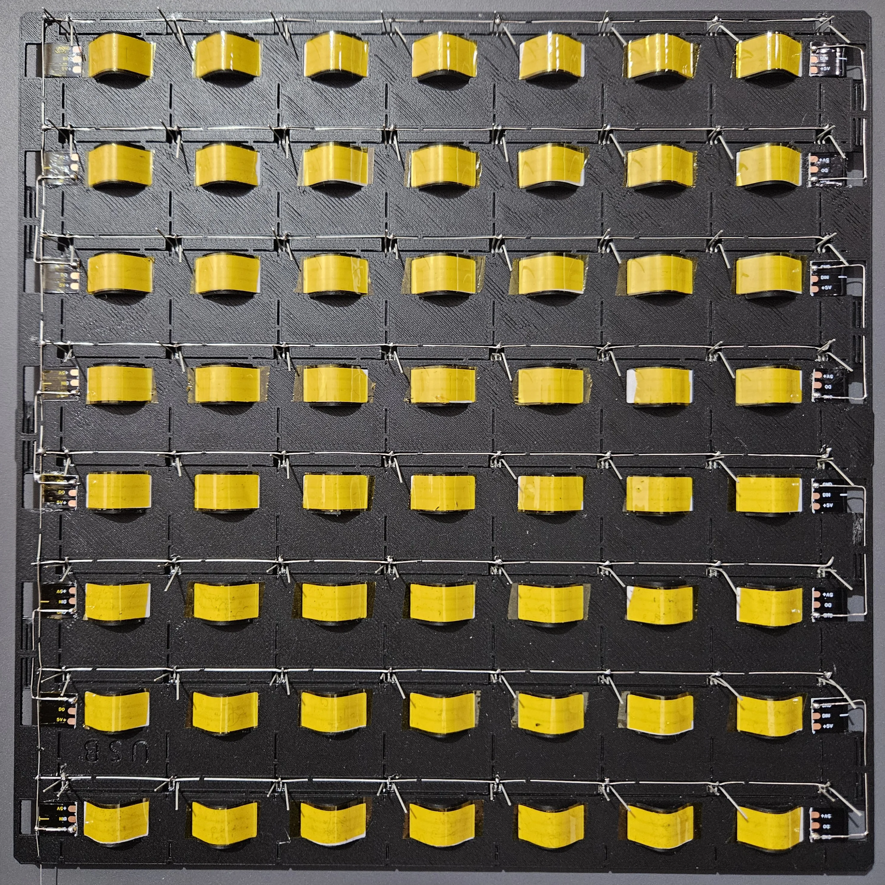
All Wires Soldered
Two perspectives showing the full sensor wiring - GND, row & column.
Completed Plastic PCB
Back and front views of the fully assembled plastic PCB - ready to be connected to the main ESP32 PCB.
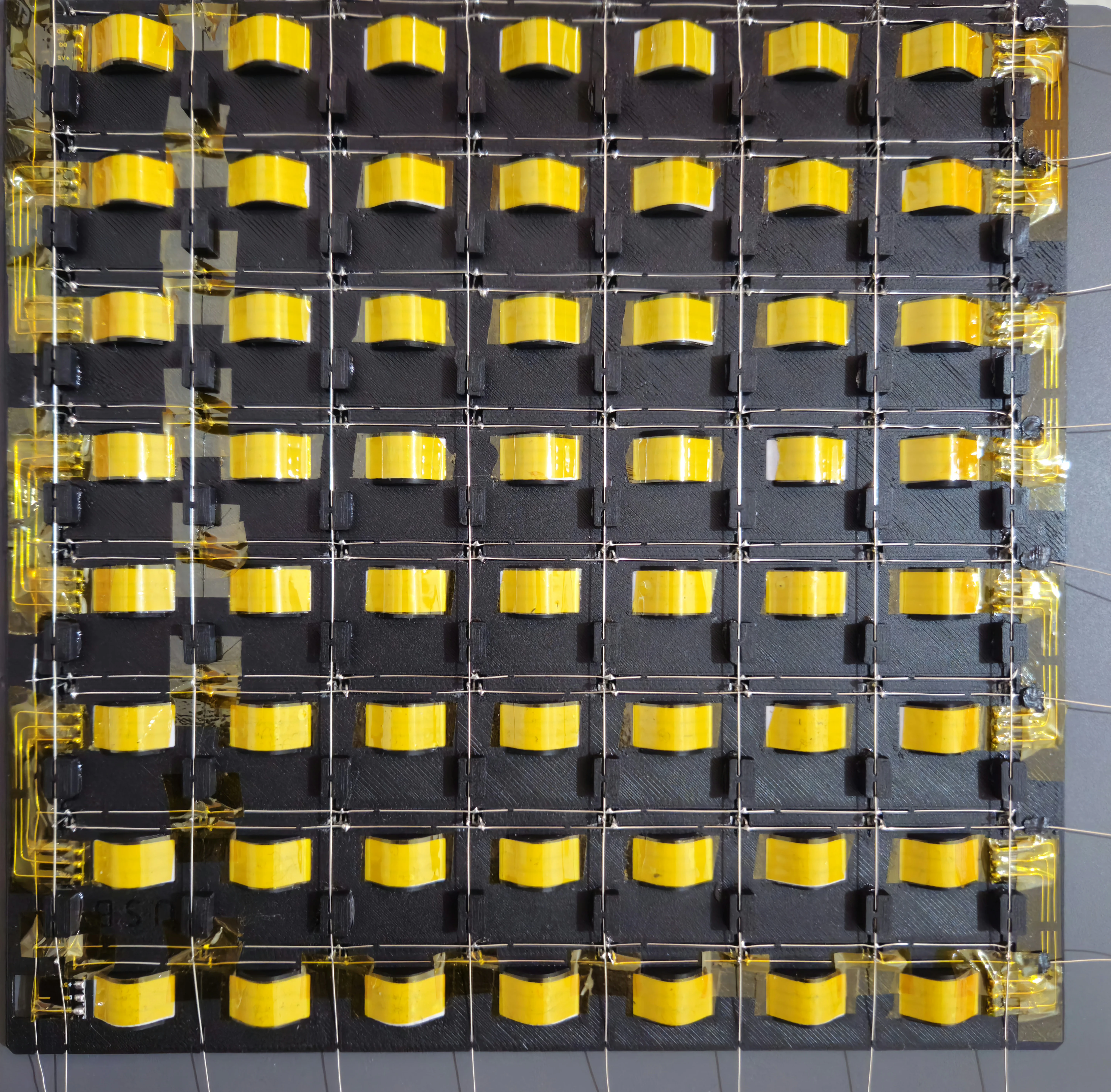 Back
Back
 Front
Front
Step 9 - Chess Pieces: Magnets & Iron Discs
Prepare the chess pieces with embedded magnets and install iron discs under the board.
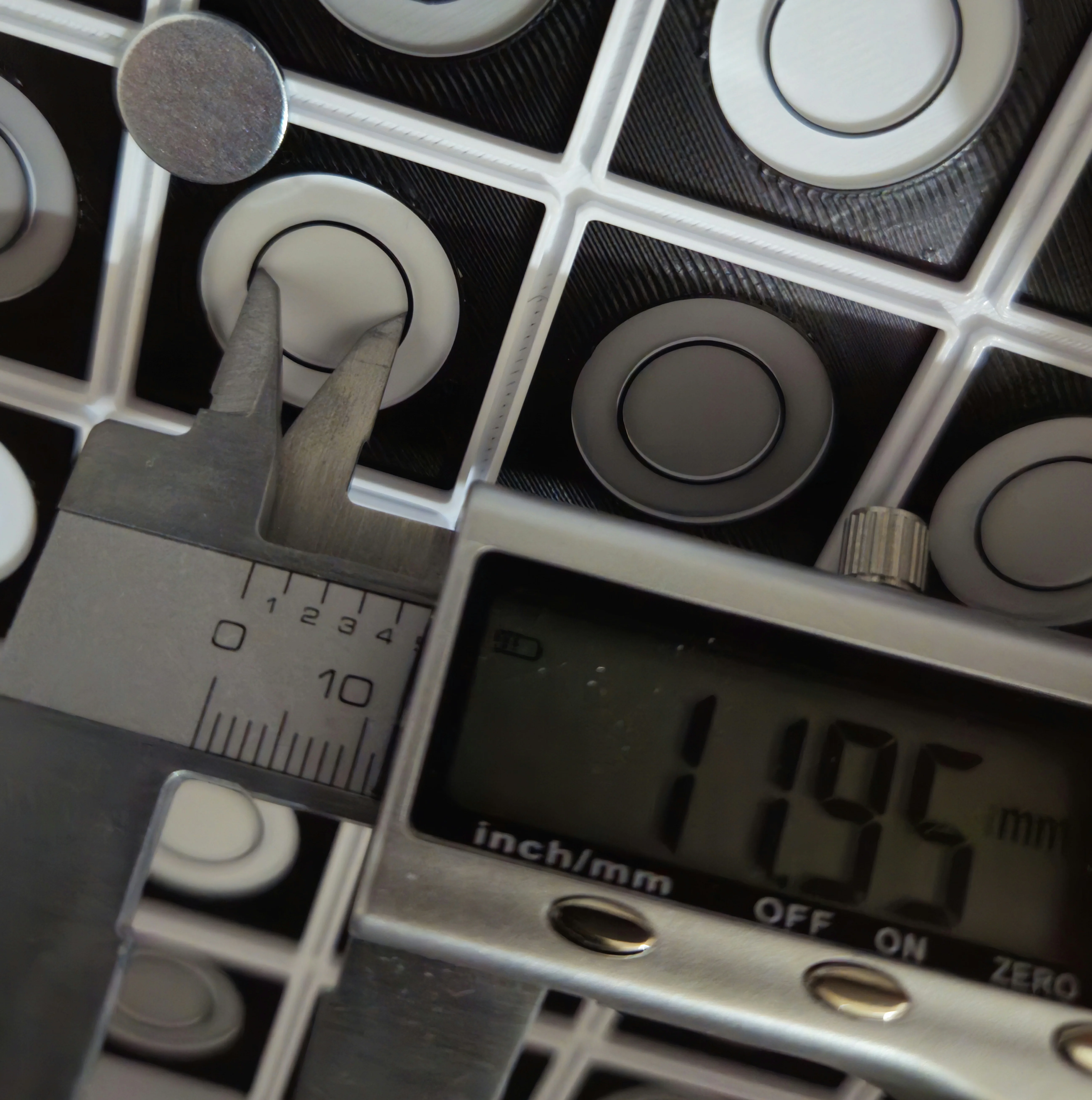
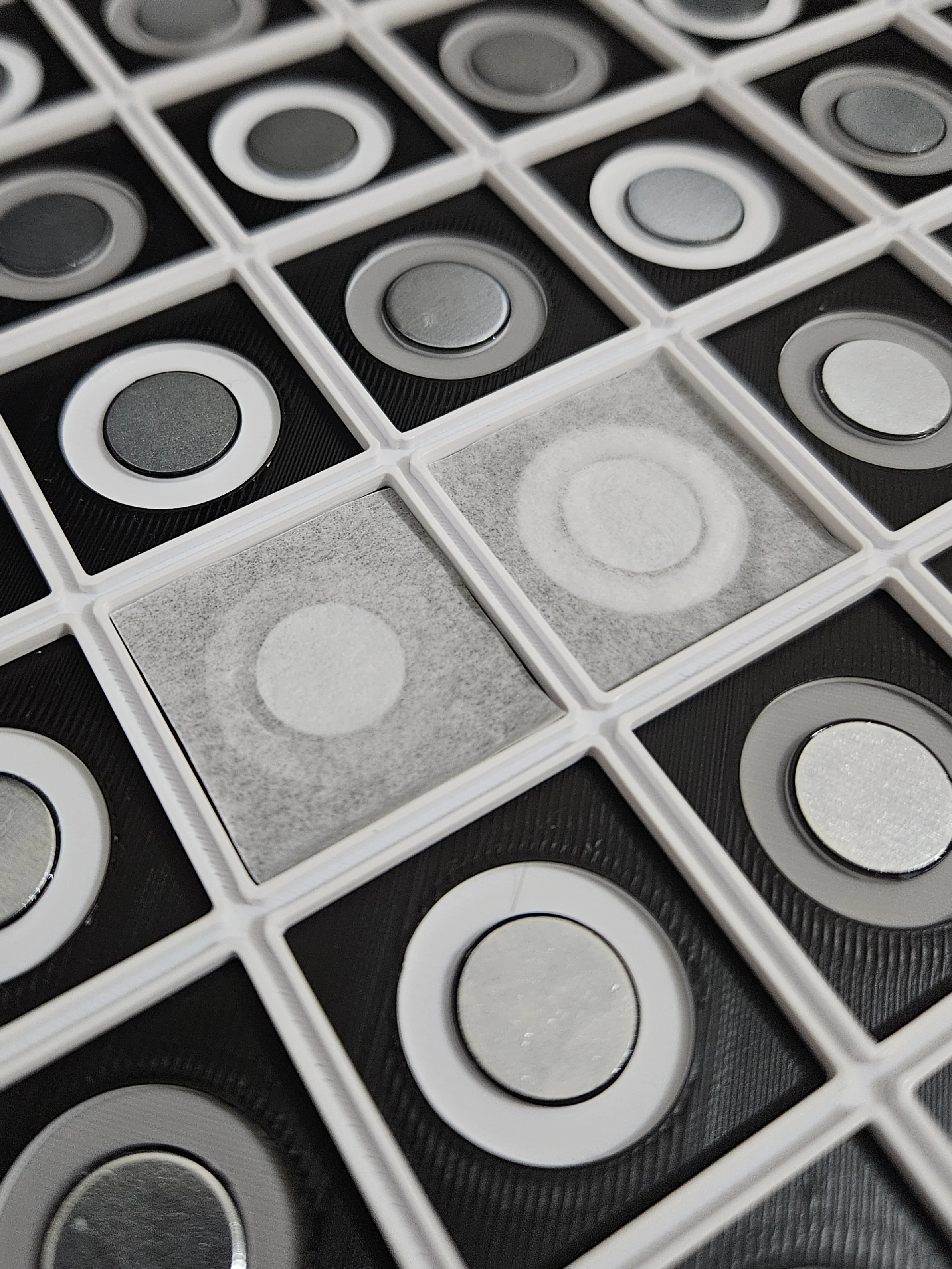
Iron Disc Size
12×1mm iron discs - these sit under each square to spread the magnetic field from the piece's magnet, making detection possible across the whole square surface. They also keep the pieces in place.
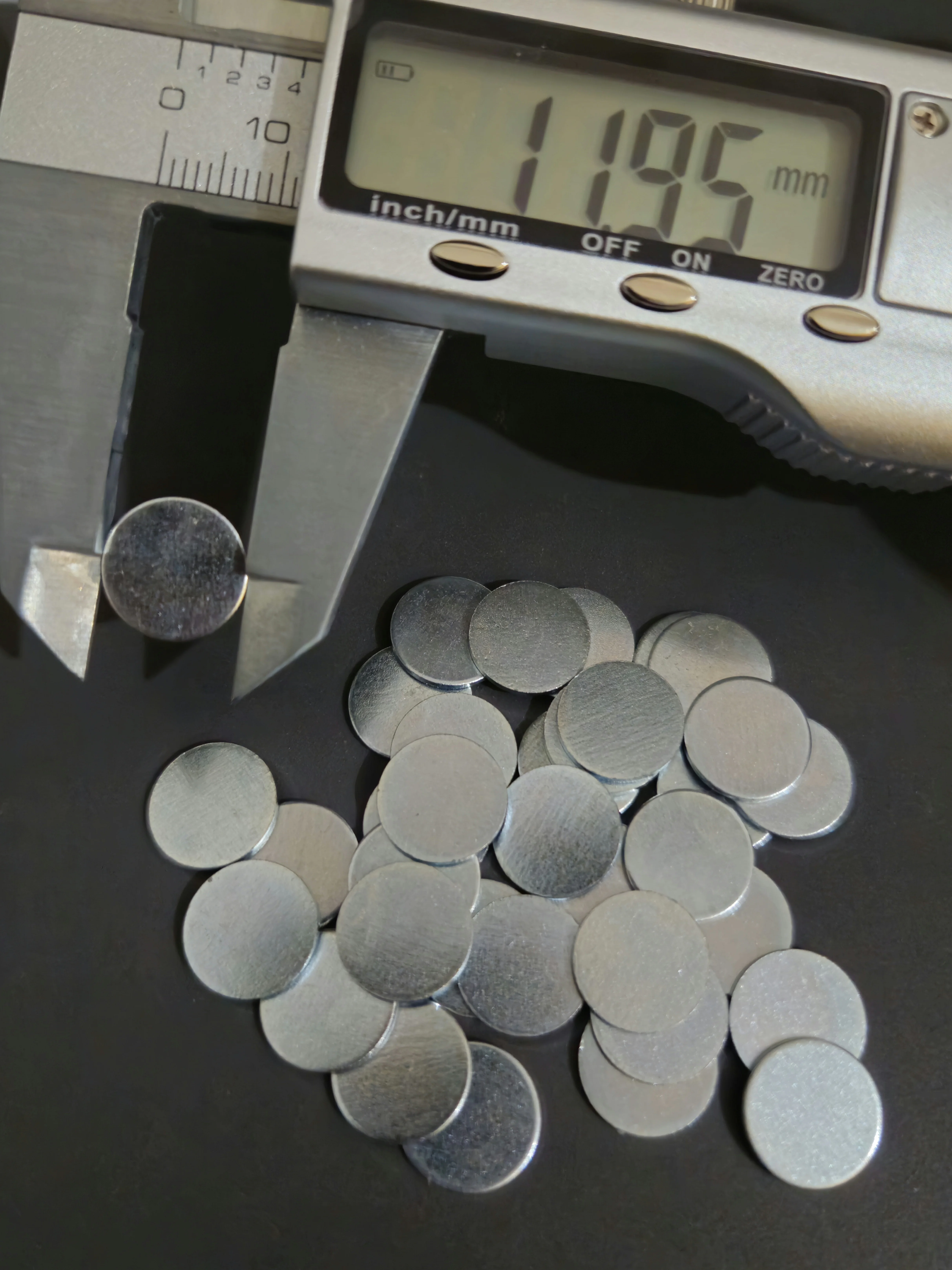 Disc diameter (12mm)
 Disc holder diameter
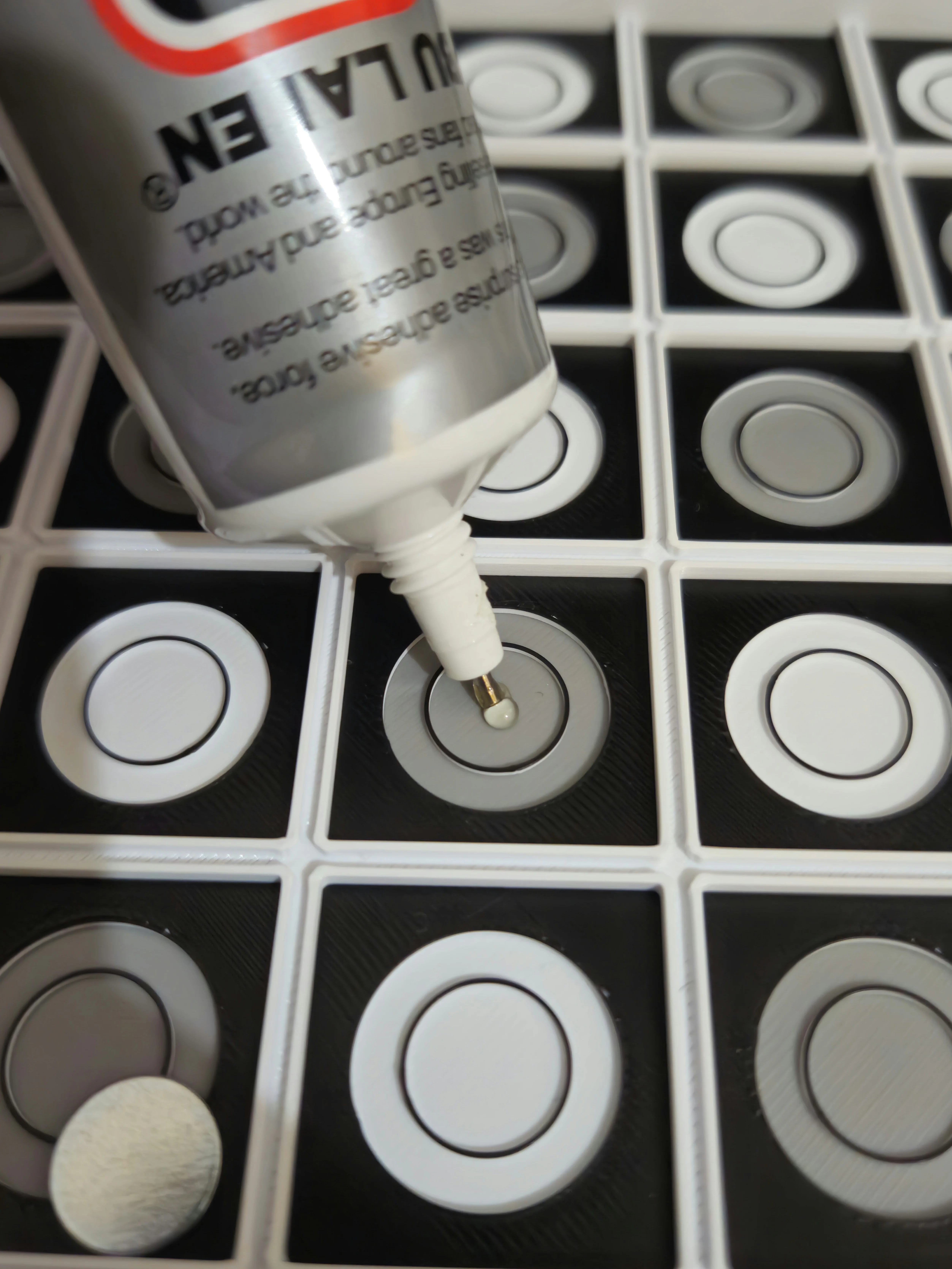
Glue Iron Discs
Glue one iron disc centered on each of the 64 squares. Make sure they're flush against the board surface and securely attached.
 Gluing
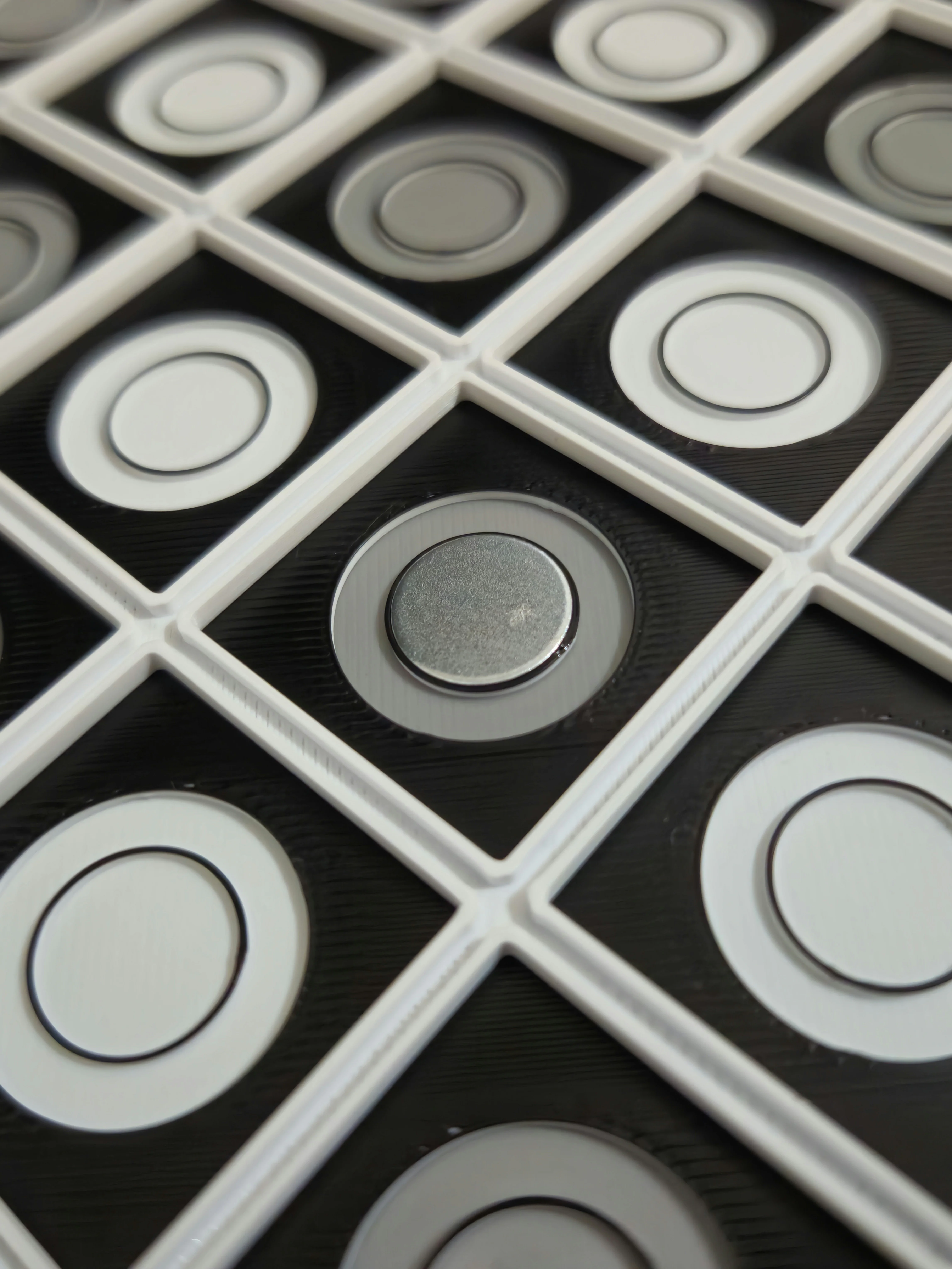 Done (1)
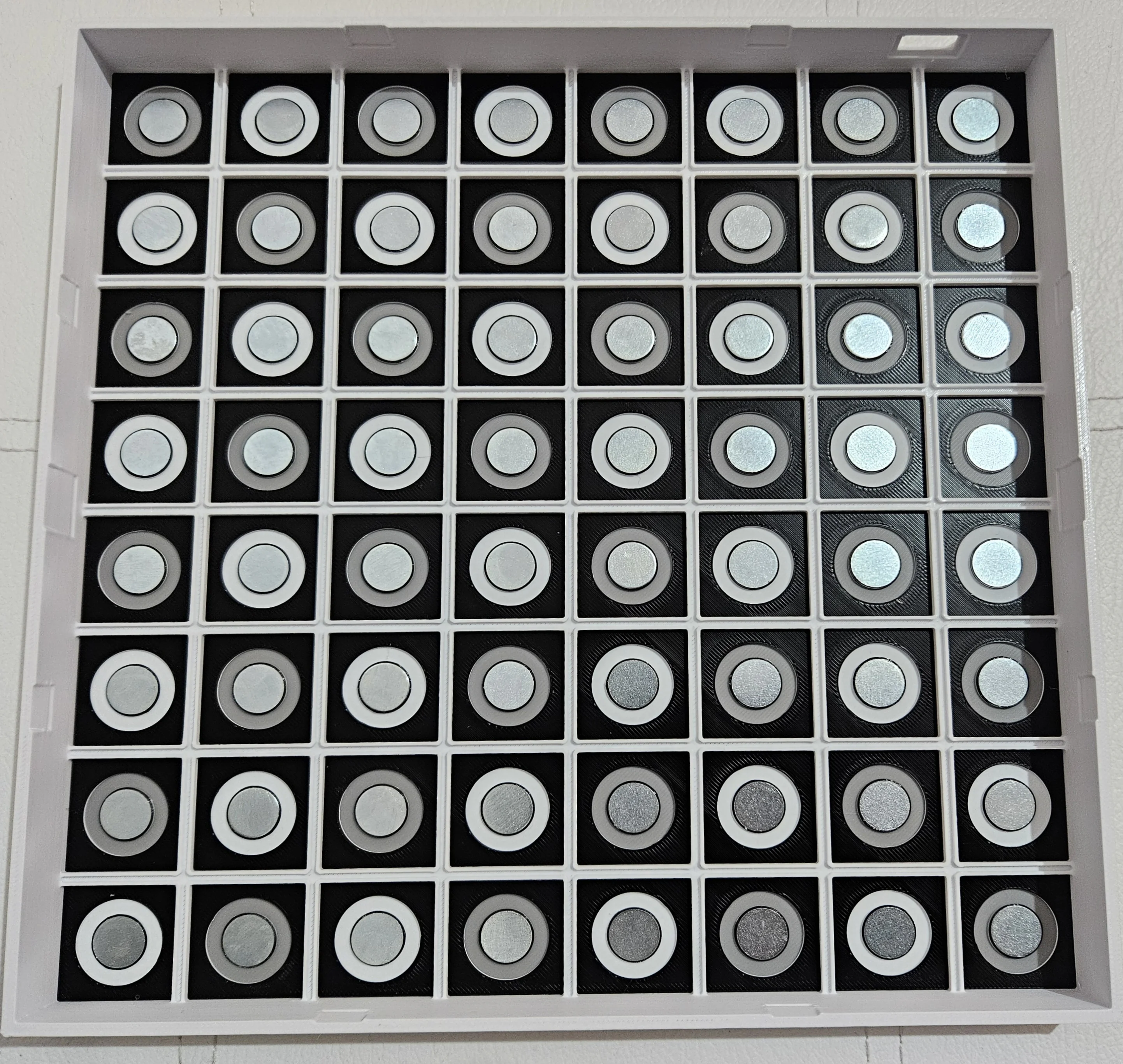 Done (64)
Glue magnets
Glue one or two neodymium magnets into the bottom of each chess piece. The magnets should be flush with the piece's base for optimal detection. Make sure to orient the magnets with the south pole facing the board! To determine which side is the south pole, simply power the board and try both sides, only 1 side will work. TIP: you can use a hairdryer to soften the PLA plastic to make inserting magnets easier
Step 10 - Board Finishing
Parchment paper can be used to diffuse the light. Do a test to make sure light shines evenly.
Glue Parchment Paper
Apply a sheet of parchment paper (baking paper) under each square. This acts as a light diffuser, spreading each LED's light evenly across the square ring, for a uniform glow without weird shadows.
Light Test & Final Look
Test how light shines through the rings. With no light backing the rings should not be visible.
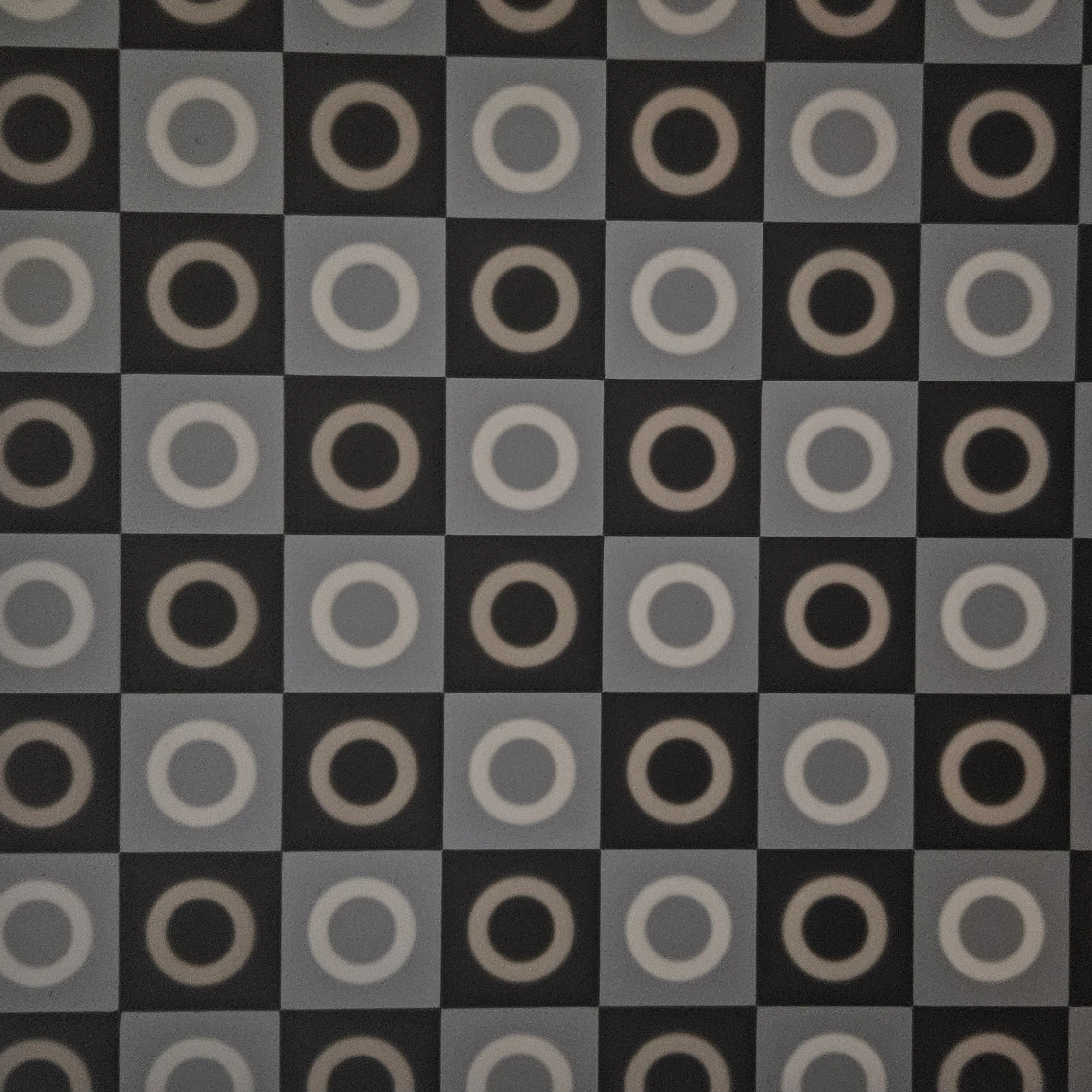 Light backing
 No light backing
Step 11 - Main PCB Connection
Connect the board's wires to the main ESP32 PCB to bring everything to life.
Apply Tape
Use double-sided tape or insulating tape on the PCB mounting area to secure it and prevent shorts against the bare metal wires.
PCB Placement
Mount the main PCB in position. Ensure it's secure and the row/column wires are oriented correctly towards their soldering pads.
Solder Rows & Columns to PCB
Solder each row wire and column wire to the correct PCB pads. Double-check against the schematic - each row wire goes to a specific GPIO pin and each column goes to a transistor output (or shift register output if not using transistors).
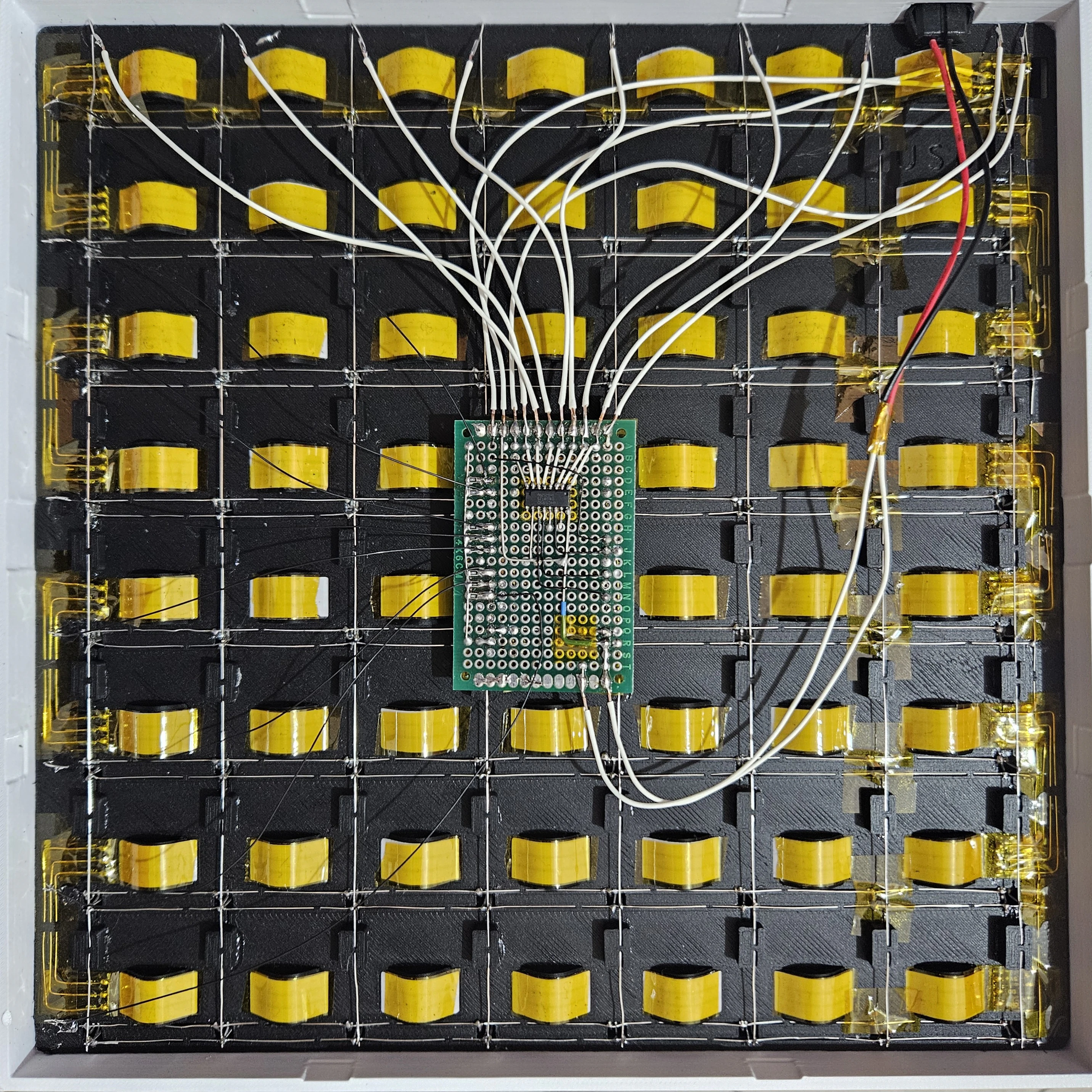 Overview
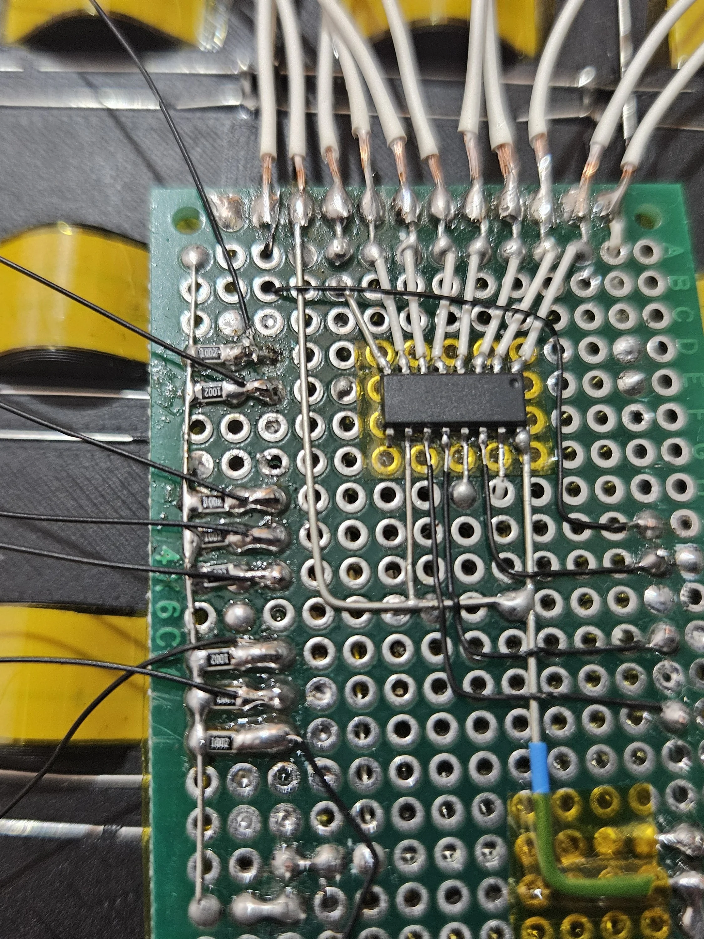 Close-up
Finished Board in Action
Here's the completed smart chess board playing a game against Stockfish. Legal moves are visualized on the board when a piece is picked up.
.webp) Bot difficulty and side selection
Bot difficulty and side selection
.webp) Human picks up Pawn, valid moves light up
Human picks up Pawn, valid moves light up
.webp) Stockfish shows the move it wants to play
Stockfish shows the move it wants to play
.webp) Human picks up Queen, valid moves light up
Human picks up Queen, valid moves light up
Demo Video
Software Setup
With the hardware built, flash the firmware to bring your chess board to life.
⚡ Quick Flash
Use the Web Installer to flash your ESP32 directly from the browser (Chrome/Edge only) Open Web InstallerChessConnect
ChessConnect is a paid premium feature with a limited free trial. It is closed-source and only included in the precompiled firmware from the Web Installer or GitHub releases.When the trial is used up, the rest of OpenChess keeps working normally but BLE board emulation stops. You can support this project and buy full access on Ko-fi:
1. Install Tools
- Install Visual Studio Code
- Install the PlatformIO IDE extension
- Install Node.js (includes
npm, needed to minify web assets) - Open a terminal and run
npm install -g html-minifier-terser clean-css-cli terser - Open the
.code-workspacefile in Visual Studio Code
2. Compile & Flash
- Connect the ESP32 via USB
- Hold the BOOT button on the ESP32
- Click Upload (Ctrl+Alt+U) in Visual Studio Code
- ⚠️ Compiling from sources won't include ChessConnect (use the Web Installer for that feature)
3. Connect to Web UI
- Connect to the OpenChess WiFi (password: chess123)
- Go to http://openchess.local to configure your board
- Click on the GPIO section to set the correct pins and transistor type (PNP/NPN) BEFORE connecting wires to GPIOs. Incorrect configuration with wires connected can cause short circuits
4. Calibrate
- After booting (or rebooting with new pins), the board enters calibration mode
- Follow the Serial Monitor Console instructions (115200 baud) to calibrate sensors and LEDs
- Calibration data is saved and only needs to be done once
5. Play!
- Power on the board - LEDs light up in the center for game selection
- Place a piece on a lit square:
- Blue - Human vs Human
- Green - Human vs Stockfish
- Yellow - Online (Lichess)
- Red - Sensor Test
- ChessConnect
- This is a paid premium feature with a limited free trial. Use the Web Installer or a GitHub release build to get firmware that includes it
- Download the ChessConnect app or extension
- In the OpenChess WebUI, choose a board to emulate and start the BLE server
- In ChessConnect, select the emulated board and connect
- Start a game right from ChessConnect
- When the trial is over, buy full access on Ko-fi to keep using ChessConnect
- Watch the video guide